The words particle and wave are two words you’ll see in nearly every area of physics, but they are actually very different from each other. A particle is a tiny concentration of something that can transmit energy, and a wave is a broad distribution of energy that fills the space it passes through. We’re going to look at particles in more depth later, and instead focus on understanding waves.
[am4show have=’p9;p58;’ guest_error=’Guest error message’ user_error=’User error message’ ]
A wave traveling along a stretched string can have different shapes, but every wave will have a frequency and a wavelength. Wavelength refers to the repeating wave shape, and frequency refers to the oscillating source that make the wave in the first place. Waves are defined by a math equation that we’ll get to a little later. First, let’s take a look at the different parts of a wave.


A wave number is the number of waves per unit length.


For longitudinal waves, a rarefaction is the spot where the the wave is traveling and is the most “stretched out” (minimum wave density). The compression is the spot where the wave is most squished together. You can see this easily if you play with a slinky… the coils that are most spread out are a rarefaction point.


Click here to go to next lesson on Period, Frequency, Amplitude and Wavelength.

[/am4show]


A wave can have many different shapes, but it has a very specific frequency ν and wavelength λ.
[am4show have=’p9;p58;’ guest_error=’Guest error message’ user_error=’User error message’ ]


Click here to go to next lesson on Humming Bird.

[/am4show]


Humming birds are really fascinating, because they can beat their wings so fast! Here’s a quick way to calculate the frequency and period of a humming bird’s wings.
[am4show have=’p9;p58;’ guest_error=’Guest error message’ user_error=’User error message’ ]


Click here to go to next lesson on Swinging Kid.

[/am4show]


Kids love swings, and it’s amazingly simple to find the frequency and period of the swing. Here’s how…
[am4show have=’p9;p58;’ guest_error=’Guest error message’ user_error=’User error message’ ]


Click here to go to next lesson on Energy and Wave Amplitude.

[/am4show]


How is the energy related to the wave frequency, amplitude and wavelength?
[am4show have=’p9;p58;’ guest_error=’Guest error message’ user_error=’User error message’ ]


Click here to go to next lesson on Wave Speed.

[/am4show]


Sound is a type of energy, and energy moves by waves. So sound moves from one place to another by waves; longitudinal waves to be more specific. So, how fast do sound waves travel? Well, that’s a bit of a tricky question. The speed of the wave depends on what kind of stuff the wave is moving through. The more dense (thicker) the material, the faster sound can travel through it.
[am4show have=’p9;p58;’ guest_error=’Guest error message’ user_error=’User error message’ ]


Remember that waves move because the particles bounce off one another? Well, the farther the particles are from one another, the longer it takes one particle to bounce off another. Think about a row of dominoes. If you put them all close together and push one over they all fall down pretty quick. If you spread them out a bit, the row falls much more slowly. Sound waves move the same way.


Click here to go to next lesson on More on Wave Speed .

[/am4show]


Sound moves faster in solid objects than it does in air because the molecules are very close together in a solid and very far apart in a gas. For example, sound travels at about 760 mph in air, 3300 mph in water, 11,400 mph in aluminum, and 27,000 mph in diamond!
[am4show have=’p9;p58;’ guest_error=’Guest error message’ user_error=’User error message’ ]


The temperature of the material also makes a difference. The colder the material, the faster the sound. This is why sound seems to be louder or clearer in the winter or at night. The air is a little cooler and since it’s cooler, the molecules are a little more tightly packed.


The speed of a wave is based on the basic distance over time relationship. If you watch the crest of a wave, the speed is how fast the crest is observed to move a distance.


Click here to go to next lesson on Echoes.

[/am4show]


An echo is when a wave travels through one medium (like air) and then meets a different medium (like a cave wall). The sound wave bounces and reflects back to you.
[am4show have=’p9;p58;’ guest_error=’Guest error message’ user_error=’User error message’ ]


Click here to go to next lesson on Bird Waves.

[/am4show]


Let’s do a couple of simpler sample problems, and then I’ll show you how to do problems that are more complex and involve higher level math. First, let’s take a look at the wings of a bird in flight…
[am4show have=’p9;p58;’ guest_error=’Guest error message’ user_error=’User error message’ ]


Click here to go to next lesson on Sitting on the Ocean.

[/am4show]


Ocean waves travel on the surface of the water can be observed and measured. Let’s try one just before a storm…
[am4show have=’p9;p58;’ guest_error=’Guest error message’ user_error=’User error message’ ]


Click here to go to next lesson on Seasick Waves.

[/am4show]


Ever gotten sea sick? It’s usually because the motion of what your body detects is different from what your eyes see. Let’s take a look at how you can calculate the wave speed by watching two boats bobbing up and down (without getting sick).
[am4show have=’p9;p58;’ guest_error=’Guest error message’ user_error=’User error message’ ]


Click here to go to next lesson on Wave Speed on Tight Strings.

[/am4show]


Waves traveling on a tight string, like a climbing rope, are dependent on only two things: the tension of the rope and a physical property of the rope (like what it’s made out of, the diameter, etc.).
[am4show have=’p9;p58;’ guest_error=’Guest error message’ user_error=’User error message’ ]


Click here to go to next lesson on Wave Equations.

[/am4show]


Now it’s time for a little more math because the physics problems are going to get a little harder.
[am4show have=’p9;p58;’ guest_error=’Guest error message’ user_error=’User error message’ ]


The wave equation for transverse and longitudinal waves moving in the +x direction looks like this:


where ym is the amplitude of the wave, κ is the angular wave number, ω is the angular frequency, and (κx-ωt) is the phase.


The wavelength L and the wave number k are found by the following equation: 


where K is the number of waves per meter.


The period (T) and the frequency (ν) are related to ω by the following equation:


The main wave speed equation is given by:


Note that the first letter v is for velocity, and the last letter in the equation is the greek letter “nu” (ν) for frequency.


The problems in the video  involve using the first equation that relates the distance and time to find the amplitude, wave number, and frequency of a wave. (This is a typical problem that you’ll see in college level physics.)


Click here to go to next lesson on Waves on a Stretched String.

[/am4show]


If a wave can travel through mediums like air, water, strings, rocks, etc., then it makes sense that as the wave moves through these mediums, the tiny particles that make up the medium will also vibrate. In order for this to happen, the medium has to have a way for energy (both potential and kinetic) to be stored, so the medium has both inertia and elasticity.
[am4show have=’p9;p58;’ guest_error=’Guest error message’ user_error=’User error message’ ]
The wave equation for a stretched spring is:


where the first letter v is for velocity, μ is the linear density of the string, and the tension is τ.


You can’t send a wave along a straight string without stretching the string. The tension in the string that does the stretching is the elasticity of the string that stores the potential energy as the wave passes through. The amount of tension in the rope will affect the wave speed. The wave speed doesn’t change if you change the frequency, however it will travel faster through a tighter rope.


This means that the speed of the wave depends on the medium, and not the wave itself. For example, waves travel faster through solid rock than they do through air because the particles in the medium are much closer together and can transmit the wave faster.


Here’s the power part of the video above explained in more detail:


Click here to go to next lesson on Behavior of Waves

[/am4show]


It’s easy to see how the current flows through a circuit that has only one component, like one LED connected to the battery. If it’s a 3 Volt battery, then there’s 3 Volts across the LED also.


But what if there are two or three LEDs? How does the voltage look across each one? What if the LEDs are different sizes? Does it matter how you hook them up, meaning does one way make the LED last monger or glow brighter? Let’s take a look at the difference between series and parallel connections.


[am4show have=’p9;p58;’ guest_error=’Guest error message’ user_error=’User error message’ ]


You can have resistors in series, batteries in parallel, motors in series and parallel, and hundreds more different combinations! It all depends on what you want to do and how you want to do it.


For example, a 6V lantern battery is actually made up of four D-cell batteries connected in series. Each D-cell is 1.5V, and when you add four of them up, you get 6V. The older models of these used to have 24 AA batteries which were connected in series and parallel to make 6V. We’re going to learn how to decide whether to use a series or parallel circuit, depending on what we’re building and what we need the circuit to do.


Which bring up another point… what’s the difference between a D-cell and a AAA battery? They both are 1.5 volts. Why use one over the other? And 9V batteries are smaller and lighter than a D-cell but have  6 times the voltage… why wouldn’t yo use 9V for everything?


It has to do with current (the rate of charge flowing through the circuit). A D-cell has much more current than a AAA battery, and you’d use D-cells for things like motors. AAA are perfect for LEDs and other low-current devices that don’t need as much amps to get them going. In your circuit, you want to choose the best option that will still work voltage and amperage-wise, is the least expensive, and lasts long enough so you’re not changing batteries every few minutes.


Click here to go to your next lesson on Series Circuits.

[/am4show]


Each electrical component is connected so that there’s only one option for the current to flow. There’s no branches or alternate routes for the electricity… it’s only got one way to move through the circuit. When you add more electrical components, like motors or LEDs to this circuit, the overall resistance in the circuit decreases since there’s only one path for the current.


[am4show have=’p9;p58;’ guest_error=’Guest error message’ user_error=’User error message’ ]


Let’s look at how charge flows through a series circuit:


Click here to go to your next lesson on Parallel Circuits.

[/am4show]


Each device, like a motor or LED, has its own branch lines in a parallel circuit, which means that the electricity has many different ways that it can travel along the circuit lines. When scientists and engineers draw electrical diagrams, they put one electric component on each branch, even if in reality there’s more than one when you actually build the thing.


[am4show have=’p9;p58;’ guest_error=’Guest error message’ user_error=’User error message’ ]


Unlike series circuits, when you add another branch, you also allow more pathways for the electricity to follow.


Click here to go to your next lesson on Calculating and Measuring Current.

[/am4show]


Current and charge aren’t quite the same thing. Current is rate that charge goes through a circuit (just like acceleration is the rate of change in velocity… acceleration and velocity aren’t the same thing either, but they are related). Remember, charge doesn’t get used up by electrical components like LEDs or resistors.


[am4show have=’p9;p58;’ guest_error=’Guest error message’ user_error=’User error message’ ]


Click here to go to your next lesson on Ohm’s Law and Current.

[/am4show]


One more thing to note about the difference between series and parallel circuits is that in a parallel circuit, the current in each branch can be different, but they all add up to be the same everywhere once you reduce the branches into a single branch. Just like the water analogy, when you connect the main hose into five different smaller hoses, the sum of all five is going to equal flow through the main hose.


[am4show have=’p9;p58;’ guest_error=’Guest error message’ user_error=’User error message’ ]


Click here to go to your next lesson on Ohm’s Law and Power.

[/am4show]


It’s easy to get sucked into doing math and equations all day without understanding how it applies to the real world. Let’s take a look at how to actually hook up series and parallel circuits in everyday life, and how they are different, and when to use each one…


[am4show have=’p9;p58;’ guest_error=’Guest error message’ user_error=’User error message’ ]


Click here to go to your next lesson on Breadboards.

[/am4show]


Although you can’t see electricity, you can certainly detect its effects – a buzzer sounding, a light flashing, a motor turning… all of these happen because of electricity. Which is why electricity experiments are among the most frustrating. You can’t always tell where the problem is in a circuit that refuses to work right.


We’re going to outline the different electronic components (resistors, capacitors, diodes, transistors, etc) so you get a better feel for how to use them in a circuit. While we’re not going to spend time on why each of these parts work (which is a topic best reserved for college courses), we are going to tackle how to use them to get your circuit to do what you want. The steps to building several different electronics projects are outlined very carefully so you can really understand this incredible micro-world.


In this video, you’ll learn how to identify each electronic component.  You’ll also learn how to use a breadboard to quickly build circuits that can be easily changed.  Plus, you’ll learn how to make sure you don’t damage your components.


Before you use a breadboard, you need to know how the “holes” in it connect to each other.  Once you get this, they’re easy to use, but until you understand their secret, they can be totally confusing.  Be sure to pay attention to this part, and it will make things a lot easier.  Once you have this down, you’ll wire up a few simple circuits on the breadboard just to try out your new knowledge.


Which part is which? Click here to access a reference sheet so you can tell which resistor is which.


[am4show have=’p8;p9;p24;p51;p58;’ guest_error=’Guest error message’ user_error=’User error message’ ]


[/am4show]


Click here to go to your next lesson on Series Switches.

Switches are a lot of fun, they allow us to control when a circuit is on and when it’s off. In this experiment we’ll see how two switches can be connected in series to control when a single device is on or off.


[am4show have=’p9;p51;p103;p108;p58;’ guest_error=’Guest error message’ user_error=’User error message’ ]


Click here to go to your next lesson on Parallel Switches.

[/am4show]


We’ve seen how switches can be used to turn stuff on and off, now let’s take a look at how a switch in different locations can turn the same thing on or off. A lot like a doorbell with a button at the front door and a button at the back door.


[am4show have=’p9;p51;p103;p108;p58;’ guest_error=’Guest error message’ user_error=’User error message’ ]


[/am4show]


Click here to go to your next lesson on Light Actuated Circuit.


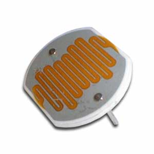
In this circuit, we’re going to use a special kind of resistor, called a CdS photocell to detect light and dark.  When light is shined on the photocell, the LED will light up.  When it is dark, the LED goes out.  And with just a little light, the LED is dim.  Remember the explanation of how a transistor works?  We talked about having a small voltage (or current) control a larger one, kind of like turning the knob on a light switch dimmer in your house?  That’s what this circuit is doing.


The photocell is a kind of resistor that changes it’s resistance depending on how light or dark it is.  In this circuit, when it is light, the photocell delivers more current to the base lead of the transistor.   When this happens, the transistor allows more voltage to flow from the emitter lead to the collector lead, which in turn lights up the LED.  One resistor are simply used to reduce the amount of current that goes into the transistor (so it doesn’t get too much current)  if the photocell has a really low resistance because of how much light is on it.  The other one is called a pull-down resistor.  Think of it like a door closer spring for electricity.  A door closer closes the door when you let go of it (instead of leaving the door to sway in the wind).  A pull-down resistor makes sure that when the transistor is “off”, it will “spring” toward a connection to the negative side of the battery (a pull-up makes it spring toward the positive).


[am4show have=’p8;p9;p24;p51;p58;’ guest_error=’Guest error message’ user_error=’User error message’ ]


If this is all confusing, don’t worry.  It will make more sense as you build more circuits and look at more schematic diagrams.


Click here for Unit 14 (Lesson 1) schematics.


This light-actuated relay circuit will remain actuated for a brief time after you remove the light.  You can substitute a 1.5-3V buzzer for the LED if you’d rather have a loud circuit.


Materials:


  • breadboard
  • AA battery case
  • 2 AA batteries
  • LED
  • CdS photocell
  • transistor (2N2222A)
  • 4.7k resistor
  • 1k resistor
  • jump wires
  • wire strippers

Here’s what you do:


[/am4show]


Click here to go to your next lesson on Light De-actuated Circuit.

Make sure you’ve already made the Light Actuated Circuit before starting this project!


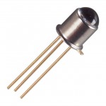
Photoresistors (also called CdS photocells) are made of a material that reacts with light, very similar to solar cells.  When light hits the material, it knocks a few electrons loose. When you hook up the cell to a circuit, the electrons now have a place to go, and electricity flows through your wires. You’ll notice your CdS cell works when you shine a light on it from either the front side or the back side. If you want to use a phototransistor, make a note as to the frequency of light it’s been tuned to – some will only work with IR light (like your remote control or sunlight).


In this circuit, the LED is actuated only when the photoresistor is dark. If you want a faster response to your light, you can substitute a phototransistor for the photoresistor (CdS cell) and adjust the value of the 1-kOhm resistor (change it lower or higher, or use a potentiometer) to control the sensitivity.


This is basically the same as the light-actuated circuit.  The difference is that the transistor is connected to control power to the LED in the opposite way as the light-actuated circuit.  So, as there is more light on the photocell (and the base lead gets more current), the voltage to the transistor is reduced.


Click here for Unit 14 (Lesson 1) schematics.


Notice what is the same in the circuit, and what is different.


[am4show have=’p8;p9;p24;p51;p58;’ guest_error=’Guest error message’ user_error=’User error message’ ]


Materials:


  • breadboard
  • AA battery case
  • 2 AA batteries
  • LED
  • CdS photocell
  • transistor (2N2222A)
  • 4.7k resistor
  • 1k resistor
  • jump wires
  • wire strippers


[/am4show]


Click here to go to your next lesson on How to Read Schematics.

Do you remember the first time you tried to read a map? There were all those weird symbols and curving lines that you had to figure out before you could get anywhere. Electric circuits are kind of the same way… people use schematic diagrams to write down how their circuit is wired so others can build it, too.


[am4show have=’p8;p9;p24;p51;p58;’ guest_error=’Guest error message’ user_error=’User error message’ ]


Now that you’ve built a couple of the breadboard circuits, it’s time to figure out how to read the symbols and build a circuit from a diagram. At first, it may seem a bit overwhelming with all the strange symbols and lines drawn all over the page, but don’t worry – after a couple of circuits, you’ll be cruising through these like a pro.


The first thing you need to do is download the schematics (if you haven’t already) and then watch this video:


Click here to go to your next lesson on Transistor Circuits.

[/am4show]


This Flashing Circuit used to be a real ‘wowser!’ with students before LEDs become commonplace (around 1995). You’re going to build a circuit that has a control knob that will allow you to set the flash speed of the LED. You can try different LEDs or mini-lamps to see what kind of an effect you get. Are you ready?


NPN and PNP transistors are similar in that when current is applied to the base, electricity flows through them.  But, they way they are used is different.  NPN transistors are often used to control whether a circuit is completed by connecting it to ground or not, where PNP control the positive current going into a device (or portion of a circuit).  NPN transistors are often used where larger currents need to be controlled, because it’s easier for a transistor to control the ground side of a circuit than the plus power side of it.


So, why does the LED flash?  Remember, a capacitor is like a storage tank for electricity.  You fill it up, then empty it out.  But, it takes time to fill up and empty.  This circuit uses the time it takes to fill and empty as a delay for turning the LED on and off.  How fast it fills up depends on the value of the resistor that is connected to it.  We’re using a variable resistor, so we can adjust how fast it fills up, and thus adjust the flash rate.


Click here for Unit 14 (Lesson 1) schematics.


[am4show have=’p8;p9;p24;p51;p58;’ guest_error=’Guest error message’ user_error=’User error message’ ]


Materials:


  • breadboard
  • AA battery case
  • 2 AA batteries
  • LED
  • potentiometer
  • transistor (2N2222A and 2N4403)
  • 5.6k resistor
  • 1k resistor
  • 10k resistor
  • jump wires
  • wire strippers


[/am4show]


Click here to go to your next lesson on Audible Probes.

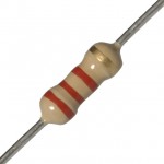
Resistors look like candy-striped hot dogs. Their job is to limit current to keep sensitive electronics from being overloaded. If you break open a resistor, you’ll find a pile of graphite. If you have a digital multimeter, draw a line on a sheet of paper with a graphite pencil, and place one probe near the end of the line. You can measure the change in resistance along the line with your other multimeter probe!


Make sure you’ve made the Light Flasher before starting this circuit. This circuit, the Audible Light Probe, is actually a very sensitive circuit that will emit all sorts of sounds reminiscent of junior high school boys locker rooms. The frequency from the speaker will change as the light intensity changes. One of the neat features about this circuit is that it will allow you to test different transistors (both PNP and NPN) to see (hear) the changes. You can also play with the capacitor and resistor values to change the range.


Click here for Unit 14 (Lesson 1) schematics.


TIP: If your tones won’t stop, or are too high to hear, try operating your circuit in a very dark room before adding the light. Can you get your speaker to *click*?


[am4show have=’p8;p9;p24;p51;p107;p58;’ guest_error=’Guest error message’ user_error=’User error message’ ]


Materials:


  • breadboard
  • AA battery case
  • 2 AA batteries
  • LED
  • CdS photocell
  • transistor (2N2222A and 2N4403)
  • 1k resistor
  • 0.47-?f electrolytic capacitor
  • 8-ohm speaker
  • jump wires
  • wire strippers


[/am4show]


Click here to go to your next lesson on Lie Detectors.

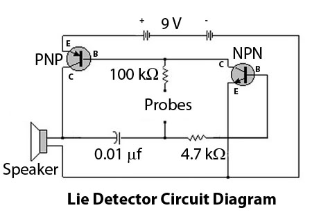
Lie Detectors are electronic circuits that are able to measure your skin’s resistance. When you sweat (or if your skin is wet), the resistance is different than if it’s dry.


However since most people don’t sweat when they lie, this type of detector isn’t the most reliable type of detector around, but it’s one of the simplest to create. We’re going to build one from simple electronic components like resistors, capacitors, and transistors.


Our lie detector uses a speaker that changes pitch depending on the resistance of your skin – it’s much more entertaining than blinking an LED on or off. You can think of this circuit as more of a skin humidity indicator. Are you ready?


[am4show have=’p8;p9;p24;p51;p107;p58;’ guest_error=’Guest error message’ user_error=’User error message’ ]
Materials:


  • Breadboard (2″x3″, 400-hole)
  • Hookup wire (AWG 22g, solid), 6 feet
  • 4.7K-ohm resistor
  • 100K-ohm resistor
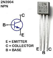
  • PN2222A or 2N3904 (NPN) transistor
  • 2N3906 or 2N4403 (PNP) transistor
  • 0.01 micro-f (mf) capacitor – Code on capacitor: 103
  • 8-ohm speaker
  • 9V battery snap and fresh 9V battery


Download your Current Electricity Problem Set here.

[/am4show]


As electrons move through a load in an electric circuit (devices like a LED, buzzer, motor, etc.), they experience resistance (even through the wire itself), which corresponds to a drop in energy . This drop in energy is referred to as a voltage drop.  Resistance hinders the flow of electrons, even in the water itself.  You can think of resistance as the friction between the water and the pipe along the inside of the pipe.


The pipe, just like the wire, has a certain diameter and length. The longer the wire, the more resistance the electron will encounter, just as with a long pipe of water. If you increase the pipe diameter, more water will flow through it. The thicker the wire, the more current flows through it. The amount of resistance the charge encounters also depends on what the wire is made out of. Certain materials are more electrically conductive than others, with silver, copper and gold being at the very low end of electrical resistance (which is why most wires are made from copper, which is the least expensive of the three).


[am4show have=’p9;p58;’ guest_error=’Guest error message’ user_error=’User error message’ ]


It’s easy to find the resistance of objects using a simple mathematical equation that relates the length of the wire, the cross-sectional area, and the resistivity of the material. Here’s an example of how to do it:


Click here to go to your next lesson on Resistance over Distance.

[/am4show]


Resistors are a very important part of electronics, in fact without them we wouldn’t even have electronics. Resistors help us control the flow of current through a circuit and protect components from being damaged. This video talks about what resistors are, how to read them, and how to use them.


[am4show have=’p9;p51;p103;p108;p58;’ guest_error=’Guest error message’ user_error=’User error message’ ]


[/am4show]


Click here to go to your next lesson on Potentiometers.

potSo now you know how to hook up a motor, and even wire it up to a switch so that it goes in forward and reverse. But what if you want to change speeds? This nifty electrical component will help you do just that.


Once you understand how to use this potentiometer in a circuit, you’ll be able to control the speed of your laser light show motors as well as the motors and lights on your robots. Ready?


[am4show have=’p8;p9;p20;p47;p106;p108;p76;p97;p58;’ guest_error=’Guest error message’ user_error=’User error message’ ]


Here’s what you need:


  • 2 AA batteries
  • AA battery case
  • 3 alligator wires
  • potentiometer
  • 1.5-3V DC motor
  • LED (any you choose)


Download Student Worksheet & Exercises


Exercises


  1. How does a potentiometer work?
  2. Does the potentiometer work differently on the LED and the motor?
  3. Name three places you’ve used potentiometers in everyday life.
  4. How do you think you might wire up an LED, switch, and potentiometer?

Click here to go to your next lesson on Measuring Voltage and Current.

[/am4show]


meterOne of the most useful tools a scientist can have! A digital multimeter can quickly help you discover where the trouble is in your electrical circuits and eliminate the hassle of guesswork. When you have the right tool for the job, it makes your work a lot easier (think of trying to hammer nails with your shoe).

We'll show you how to get the most out of this versatile tool that we're sure you're going to use all the way through college. This project is for advanced students.

[am4show have='p9;p47;p107;p76;p58;' guest_error='Guest error message' user_error='User error message' ]


Download Student Worksheet & Exercises

Exercises

  1. If you measure 2.65 volts from your battery pack, do you need new batteries or will they work?
  2. How do you think you would measure the resistance of an LED?
  3. Reset your meter for a quick practical test: Remove the wires from your DMM and set the dial at OFF. Wave your hand wildly and show how you can use the meter (you can add probes and turn it on now) to test the voltage on your LED in a simple circuit doing the steps from the experiment.

[/am4show]

Click here to go to your next lesson on Ohm's Law.


One of the most important equations in current electricity is: V = IR. With one glance, you can see how current, voltage, and resistance are related to each other. If the current decreases, so does the voltage. Charge  mores when the resistance decreases.


[am4show have=’p9;p58;’ guest_error=’Guest error message’ user_error=’User error message’ ]


Click here to go to your next lesson on Applying Ohm’s Law.

[/am4show]


There are two main equations for power in the field of current electricity:


P = I2 R


P = V2/R


where P = power (watts), V = voltage (volts), R = resistance (ohms), I = current (amps)


[am4show have=’p9;p58;’ guest_error=’Guest error message’ user_error=’User error message’ ]


Using these three equations (the two above and V = IR) will solve most of your problems in physics having to do with current electricity. However, there are a few things to keep in mind before you dive in too deeply…


Click here to go to your next lesson on Hair Dryers.

[/am4show]


I do have a LOT of hair on my head. Here’s a neat way to figure out how much current I use every morning I fire up the hair dryer:


[am4show have=’p9;p58;’ guest_error=’Guest error message’ user_error=’User error message’ ]


Click here to go to your next lesson on Toasters.

[/am4show]


Imagine you have two metal plates that are parallel to each other, and one is positively charged ad the other is negatively charged. The direction of the electric field created by these two charged places is from the positive toward the negative plate. (Imagine placing a positive test charge int he field… which way would it go? Away from the positive plate and toward the negative plate… so that’s the direction of the electric field.) Now imagine connecting the two plates with a metal wire. What do you think would happen?


[am4show have=’p9;p58;’ guest_error=’Guest error message’ user_error=’User error message’ ]


The positive charges on the positive plate would flow toward the negative plate, evening out the charge until they were both at the same charge, and then there is no electric potential difference between the two. It’s like connecting a hose between two cups filled with different levels of water. The water flows out of the cup with more water into the one with less until they both even out. When the charges even out, there not charge flow because there’s no electrical potential difference.


Click here to go to your next lesson on Electric Circuits!

[/am4show]


An electrical circuit is like a NASCAR raceway.  The electrons (racecars) zip around the race loop (wire circuit) superfast to make stuff happen. Although you can’t see the electrons zipping around the circuit, you can see the effects: lighting up LEDs, sounding buzzers, clicking relays, etc.


There are many different electrical components that make the electrons react in different ways, such as resistors (limit current), capacitors (collect a charge), transistors (gate for electrons), relays (electricity itself activates a switch), diodes (one-way street for electrons), solenoids (electrical magnet), switches (stoplight for electrons), and more.  We’re going to use a combination diode-light-bulb (LED), buzzers, and motors in our circuits right now.


A CIRCUIT looks like a CIRCLE.  When you connect the batteries to the LED with wire and make a circle, the LED lights up.  If you break open the circle, electricity (current) doesn’t flow and the LED turns dark.


LED stands for “Light Emitting Diode”.  Diodes are one-way streets for electricity – they allow electrons to flow one way but not the other.


Remember when you scuffed along the carpet?  You gathered up an electric charge in your body.  That charge was static until you zapped someone else.  The movement of electric charge is called electric current, and is measured in amperes (A). When electric current passes through a material, it does it by electrical conduction. There are different kinds of conduction, such as metallic conduction, where electrons flow through a conductor (like metal) and electrolysis, where charged atoms (called ions) flow through liquids.


[am4show have=’p8;p9;p20;p47;p106;p76;p97;p58;’ guest_error=’Guest error message’ user_error=’User error message’ ]


Here’s what you need:


  • 2 AA batteries
  • AA battery case
  • 2 alligator wires
  • LEDs (any you choose is fine)


Download Student Worksheet & Exercises


Be alert for:


1. Batteries inserted into the case the wrong way!


2. LED in the wrong way (LEDs are picky about plus and minus – they are POLARIZED)


3. Is there a metal-to-metal connection?  (You’re not grabbing ahold of the plastic insulation, are you?)


4. Bad wires can cause headaches – if all else fails, then swap out your alligator clip lead wires for new ones.


Exercises


  1. What does LED stand for?
  2. Does it matter which way you wire an LED in a circuit?
  3. Does the longer wire on the LED connect to plus (red) or minus (black)?
  4. Do you need to hook up batteries to make a neon bulb light up?  Why or why not?
  5. What’s the difference between a light bulb and your LED?
  6. What is the difference between a bolt of lightning and the electricity in your circuit?
  7. What is the charge of an electron?

[/am4show]


Click here to go to your next lesson on Detecting Current!

Galvanometers are coils of wire connected to a battery. When current flows through the wire, it creates a magnetic field. Since the wire is bundled up, it multiplies this electromagnetic effect to create a simple electromagnet that you can detect with your compass.
[am4show have=’p8;p9;p21;p48;p106;p77;p58;’ guest_error=’Guest error message’ user_error=’User error message’ ]
Here’s what you need to do:


Materials:


  • magnet wire
  • sand paper
  • scissors
  • compass
  • AA battery case
  • 2 AA batteries
  • 2 alligator clip wires


Download Student Worksheet & Exercises


1. Remove the insulation from about an inch of each end of the wire. (Use sandpaper if you’re using magnet wire.)


2. Wrap the wire at least 30-50 times around your fingers, making sure your coil is large enough to slide the compass through.


3. Connect one end of the wire to the battery case wire.


4. While looking at the compass, repeatedly tap the other end of the wire to the battery. You should see the compass react to the tapping.


5. Switch the wires from one terminal of the battery to the other. Now tap again. Do you see a difference in the way the compass moves?


You just made a simple galvanometer. “Oh boy, that’s great! Hey Bob, take a look! I just made a….a what?!?” I thought you might ask that question. A galvanometer is a device that is used to find and measure electric current. “But, it made a compass needle move…isn’t that a magnetic field, not electricity?” Ah, yes, but hold on a minute. What is electric current…moving electrons. What do moving electrons create…a magnetic field! By the galvanometer detecting a change in the magnetic field, it is actually measuring electrical current! So, now that you’ve made one let’s use it!


More experiments with your galvanometer

You will need:


  • Your handy galvanometer
  • The strongest magnet you own
  • Another 2 feet or more of wire
  • Toilet paper or paper towel tube

1. Take your new piece of wire and remove about an inch of insulation from both ends of the wire.


2. Wrap this wire tightly and carefully around the end of the paper towel tube. Do as many wraps as you can while still leaving about 4 inches of wire on both sides of the coil. You may want to put a piece of tape on the coil to keep it from unwinding. Pull the coil from the paper towel tube, keeping the coil tightly wrapped.


3. Hook up your new coil with your galvanometer. One wire of the coil should be connected to one wire of the galvanometer and the other wire should be connected to the other end of the galvanometer.


4. Now move your magnet in and out of the the coil. Can you see the compass move? Does a stronger or weaker magnet make the compass move more? Does it matter how fast you move the magnet in and out of the coil?


Taa Daa!!! Ladies and gentlemen you just made electricity!!!!! You also just recreated one of the most important scientific discoveries of all time. One story about this discovery, goes like this:


A science teacher doing a demonstration for his students (can you see why I like this story) noticed that as he moved a magnet, he caused one of his instruments to register the flow of electricity. He experimented a bit further with this and noticed that a moving magnetic field can actually create electrical current. Thus tying the magnetism and the electricity together. Before that, they were seen as two completely different phenomena!


Now we know, that you can’t have an electric field without a magnetic field. You also cannot have a moving magnetic field, without causing electricity in objects that electrons can move in (like wires). Moving electrons create a magnetic field and moving magnetic fields can create electric currents.


“So, if I just made electricity, can I power a light bulb by moving a magnet around?” Yes, if you moved that magnet back and forth fast enough you could power a light bulb. However, by fast enough, I mean like 1000 times a second or more! If you had a stronger magnet, or many more coils in your wire, then you could make a greater amount of electricity each time you moved the magnet through the wire.


Believe it or not, most of the electricity you use comes from moving magnets around coils of wire! Electrical power plants either spin HUGE coils of wire around very powerful magnets or they spin very powerful magnets around HUGE coils of wire. The electricity to power your computer, your lights, your air conditioning, your radio or whatever, comes from spinning magnets or wires!


“But what about all those nuclear and coal power plants I hear about all the time?” Good question. Do you know what that nuclear and coal stuff does? It gets really hot. When it gets really hot, it boils water. When it boils water, it makes steam and do you know what the steam does? It causes giant wheels to turn. Guess what’s on those giant wheels. That’s right, a huge coil of wire or very powerful magnets! Coal and nuclear energy basically do little more than boil water. With the exception of solar energy almost all electrical production comes from something huge spinning really fast!


Exercises


  1. Why didn’t the coil of wire work when it wasn’t hooked up to a battery? What does the battery do to the coil of wire?
  2. How does a moving magnet make electricity?
  3. What makes the compass needle deflect in the second coil?
  4. Does a stronger or weaker magnet make the compass move more?
  5. Does it matter how fast you move the magnet in and out of the coil?

Click here to go to your next lesson on Conductivity!

[/am4show]


switch-zoomMake yourself a grab bag of fun things to test: copper pieces (nails or pipe pieces), zinc washers, pipe cleaners, Mylar, aluminum foil, pennies, nickels, keys, film canisters, paper clips, load stones (magnetic rock), other rocks, and just about anything else in the back of your desk drawer.


Certain materials conduct electricity better than others. Silver, for example, is one of the best electrical conductors on the planet, followed closely by copper and gold. Most scientists use gold contacts because, unlike silver and copper, gold does not tarnish (oxidize) as easily. Gold is a soft metal and wears away much more easily than others, but since most circuits are built for the short term (less than 50 years of use), the loss of material is unnoticeable.
[am4show have=’p8;p9;p20;p47;p76;p97;p58;’ guest_error=’Guest error message’ user_error=’User error message’ ]


Modify your basic LED circuit into a Conductivity Circuit by removing one clip lead from the battery and inserting a third clip lead to the battery terminal. The two free ends are your new clips to put things in from the grab bag. Try zippers, metal buttons, barrettes, water from a fountain, the fountain itself, bike racks, locks, doorknobs, unpainted benches… you get the idea!


Here’s what you need:


  • 2 AA batteries
  • AA battery case
  • 3 alligator wires
  • LEDs (any you choose is fine)
  • paper clip
  • penny
  • other metal objects around your house (zippers, chairs, etc…)


Why does metal conduct electricity?

Why does metal, not plastic, conduct electricity? Imagine you have a garden hose with water flowing through it. The hose is like the metal wire, and the water is like the electric current. Trying to run electricity through plastic is like filling your hose with cement. It’s just the nature of the material.


Download Student Worksheet & Exercises


Exercises


  1.       Name six materials that are electrically conductive.
  2.        What kinds of materials are conductors and insulators?
  3.      Can you convert an insulator into a conductor? How?
  4.        Name four instances when insulators are a bad idea to have around.
  5.      When are insulators essential to have?

[/am4show]


Click here to go to your next lesson on requirements for a circuit!

You need two important things for an electric circuit: first you need a closed conductive path that goes from the positive to the negative terminal of the battery. When I teach this activity to kids, there’s always a couple that try to light up the LED just using the LED and wires (they forget about the battery completely!) You always need a power source in the circuit in order for charges to flow. The charges only flow through something that conducts electricity. Sometimes kids forget about the conductive part, and just try to touch the plastic coating on the wires to the LED and are frustrated when it doesn’t work right. It must be a closed conductive loop.


[am4show have=’p9;p58;’ guest_error=’Guest error message’ user_error=’User error message’ ]


The second thing is that there needs to be an electric potential difference across the two ends of the circuit. (You can think of the ends as the ends that are connected to the battery.) Because it takes energy to move the charge from a low to a high potential (remember how it takes energy to go up a flight of stairs?), there needs to be something that supplies the charges with the energy they need to go from a low to a high electric potential so then they can move through the circuit on their own. As the charge moves though the circuit, it loses energy until it reaches the negative terminal at zero energy. Then the battery gives that charge energy and it moves back up to the positive terminal at high energy and does it all over again. The battery pumps up the charges and creates an electric potential difference across the two ends of the circuit.


In your house, the electric outlet that you plug appliances and lamps into is the electric potential difference. The three holes in the outlet are hot, neutral, and ground.


The hot terminal is the smaller one on the upper right, and this has the highest potential. Neutral is the larger one on the upper left, and it is the return path for current (and should always be considered to be high potential. It’s unfortunately pretty common for hot and neutral wiring to be reversed, because the outlet still works if it is.) Ground is the roundish one at the bottom and is there for safety. Ground and neutral are connected together back at the box, and they give electricity the quickest and simplest way back to the low potential.  An ungrounded device (including extension cords) can be dangerous if there’s no path to ground except through you.


The electrical outlet in US homes supplies 110-120 volts of voltage and 15-20 amps of current. On the other hand, a AA battery has 1.5 volts and about 50 mA (that;s 0.050 amps), depending on the type of battery and what kind of load you are putting on it.


And just in case you’re considering poking something into the outlet, over 4,000 people every year are in the emergency room for injuries that have to do with sticking something other than a plug into an electrical outlet, about one third of them are kids under 18 years old. And those are just the ones you made it to the hospital… some were not as lucky and never made it at all. The current can kill you because you’re made up mostly of water, which makes it a really good conductor of electricity. Electricity is always looking for the easiest way to ground, and though you is one of those ways and the amount of current that passes through you is enough to stop your heart and damage your cells. Bottom line: the only thing you should put into an outlet is a plug.


Click here to go to your next lesson on the water analogy!

[/am4show]


This is a recording of a recent live robotics teleclass I did with thousands of kids from all over the world. I’ve included it here so you can participate and learn, too!


We’ll cover topics in electricity, magnetism, electrical charges, robot construction, sensors and more by building several projects together. For now, just watch the video and if you already have the materials to build the projects, feel free to do it along with me. If not, don’t worry… we’ll get to these projects soon in the course.


[am4show have=’p9;p58;’ guest_error=’Guest error message’ user_error=’User error message’ ]


Materials:


  • AA battery case (Jameco 216081)
  • Two AA batteries for your battery case**
  • A couple of LEDs (You can use any under 3V, but if you need recommendations, try Jameco 2-lead LEDs or 3-lead LEDs)
  • Set of 10 alligator wires (Jameco 10444)
  • One or two 1.5-3V DC motors (Jameco 231925)
  • Index card
  • 6 brass fasteners
  • Two large paper clips
  • One foam block (2” cube or larger)
  • 1 wooden clothespin
  • 10 wooden skewers
  • Drill & bit the size of the motor shaft diameter
  • Hot glue gun, razor and adult assistant
  • OPTIONAL: Buzzer (Jameco 24872)

**Note about batteries: The cheap dollar-store kind labeled “Heavy Duty” are recommended. Do not use alkaline batteries like “Duracell” or “Energizer” for your experiments with us during this class. (We’ll explain during the class.)


Download the worksheet for this teleclass HERE.


Key Concepts

A robot not only moves but it can also interact with its environment and it does that by using sensors, like light detectors that can see light, you can have motion detectors that can sense movement, touch sensors, pressure sensors, infrared light sensors, proximity sensors, water detectors, spit sensors, detecting all different kinds of stuff!


Robots need electricity to make the motors move, the LEDs light up, the buzzers to sound, and more. When you move electrons around, that’s what creates the electricity. When you rub a balloon on your head for example, you’re picking off the electrons from the atoms in your hair and sticking them on the balloon. There’s a static charge on your head due to the extra electrons.


The electrons have a negative charge, and so just like the north and south poles of a magnet attract each other, the negative charge of the electron is attracted to positive charges. That’s why your batteries have plus and minus signs on them. Electricity is when the electric charge is moving around inside the wires in the circuit.


Current is measured in amps, and is a measure of how much charge is flowing through the circuit at a certain point. We use the letter to mean current when we’re doing calculations on paper, and it’s important to remember that current is like velocity in that it’s a rate.Just like velocity is the change in position per unit time, current is the amount of charge per unit time: I = Q/t. This means that one amphere (amp) is one coulomb per second.


Click here to go to your next lesson on Franklin’s Mistake!

[/am4show]


If this next part is too confusing, just skip over it. I did want to let you know (for those of you who have spotted it already) that there’s a big problem with the positive test charge model we’ve been using. Well, it’s kind of a problem, but not really a big one once you get used to the idea.


[am4show have=’p9;p58;’ guest_error=’Guest error message’ user_error=’User error message’ ]


When we determined which one is the high and low potential (the plus and minus on a battery), we assumed that the test charge was positive. The particles that move charge through the wires are actually negatively, not positively, charged. We’ve been dealing with just positive charges so far, and now we’re going to mix things up a bit since electrons are in fact, negative. This means that current actually goes from the negative terminal to the positive terminal because that charge is being carried by electrons. Note that charge carriers don’t have to be electrons (they can also be positively charged or both traveling simultaneously in opposite directions!)


It was actually one of Ben Franklin’s not-so-great moments when he arbitrarily assigned the direction of electric current the way we think about it today, which is going from the positive to the negative terminal. Electrons actually move in  the opposite direction! BUT in the real world, we all think about current flowing from plus to minus (even though in reality its the opposite direction). Just file it away in your mind in case it ever comes up (which it probably won’t) that you would need to know the actual direction the electrons are moving in a circuit (which most people don’t need to know or care about).


Click here to go to your next lesson on learning about charge carriers!

[/am4show]


In electric circuits, the charge carriers are electrons, which are already inside the wire itself. The battery doesn’t add extra electrons to the circuit to make it go… the electrons inside the wires are already there. The battery provides an electric potential difference that signals the electrons to start moving, and this signal travels at the speed of light (or close to it), and then the electrons start moving (quite a bit slower than the speed of light). This means that electrons don’t have to start at the battery and them go all the way to the light before the light bulb lights up, because the electrons inside the filament itself are the ones that start glowing when they get the signal to start moving.


[am4show have=’p9;p58;’ guest_error=’Guest error message’ user_error=’User error message’ ]


All electrons everywhere start moving as soon as they get that signal from the battery, like like water flowing in the hose that we saw in the teleclass video. The electrons themselves don’t get used up, but rather the energy carried by the electrons is transformed to other forms of energy (including heat, light, sound, motion, etc.). The charge itself doesn’t transform or get used up, just the energy itself. Kids use up their energy as they run, play, and jump , and need to refuel before they can go back in the afternoon to the playground. The kids don’t get used up, but rather the energy the kid is carrying is being transformed from chemical energy int the food to motion energy , and needs to be replenished when the kid runs out of energy.


Click here to go to your next lesson on Switches!

[/am4show]


knifeswitchWhen you turn on a switch, it’s difficult to really see what’s going on… which is why we make our own from paperclips, brass fasteners, and index cards.


Kids can see the circuit on both sides of the card, so it makes sense why it works (especially after doing ‘Conductivity Testers’).


SPST stands for Single Pole, Single Throw, which means that the switch turns on only one circuit at a time. This is a great switch for one of the robots we’ll be making soon, as it only needs one motor to turn on and off.
[am4show have=’p8;p9;p20;p47;p106;p108;p97;p58;’ guest_error=’Guest error message’ user_error=’User error message’ ]


Think of this switch like a train track. When you throw the switches one way, the train (electrons) can race around the track at top speed. When you turn the switch to the OFF position, it’s like a bridge collapse for the train – there’s no way for the electrons to jump across from the brass fastener to the paper clip. When you switch it to the ON position (both sides), you’ve rebuilt the bridges for the train (electrons).


Troubleshooting: The two tabs on the back of the motor are the places to clip in the power from the battery pack. Since these motors spin quickly and the shaft is tiny, add a piece of tape to the shaft to see the spinning action more clearly.


Kids can make their own switches so they can trace the path the electricity takes with a finger. See what you think about this SPST:


Here’s what you need:


  • 2 AA batteries
  • AA battery case
  • 3 alligator wires
  • index card
  • 2 brass fasteners
  • paper clips
  • buzzer, motor, or LED


Download Student Worksheet & Exercises


Exercises


  1.  If you want to reverse the spin direction of a motor without using a switch, what can you do?
  2.  A simple switch can be made out of what kinds of materials?
  3.  How would you make your SPST switch an NC (normally closed) switch?
  4.  How did you have to connect your circuit in order for both the LED and motor to work at the  same time? Draw it here:
  5.  Draw a picture of your experiment that explains how the SPST switch works, and show how      electricity flows through your circuit:

Extra Credit (for students who have completed Part 3):


  1. Draw a picture of your experiment that explains how the DPDT switch works in your circuit and show how to wire up the circuit.

[/am4show]


 Click here to go to your next lesson on Electric Circuit Loads!

Imagine you have two magnets. Glue one magnet on an imaginary record player (or a ‘lazy susan’ turntable) and hold the other magnet in your hand. What happens when you bring your hand close to the turntable magnet and bring the north sides together?


The magnet should repel and move, and since it’s on a turntable, it will circle out of the way. Now flip your hand over so you have the south facing the turntable. Notice how the turntable magnet is attracted to yours and rotates toward your hand. Just as it reaches your hand, flip it again to reveal the north side. Now the glued turntable magnet pushes away into another circle as you flip your magnet over again to attract it back to you. Imagine if you could time this well enough to get the turntable magnet to make a complete circle over and over again… that’s how a motor works!


After you get the buzzer and the light or LED to work, try spinning a DC motor:


[am4show have=’p8;p9;p20;p47;p106;p76;p97;p58;’ guest_error=’Guest error message’ user_error=’User error message’ ]


Here’s what you need:


  • 2 AA batteries
  • AA battery case
  • 2 alligator wires
  • 1.5-3V DC motor
  • optional: propeller


Click here to go to your next lesson on Power!

[/am4show]


We’re going to define power in an electric circuit as the rate tat electrical energy is used by the load (or supplied by the source). Power is then equal to the work done by the charge per unit time, or said another way, the rate that the charge changes its energy (whether it’s lost or gained).


[am4show have=’p9;p58;’ guest_error=’Guest error message’ user_error=’User error message’ ]


For a battery, the charge gains energy so it’s a positive quantity, and in the devices in the circuit (the load), energy is lost, so the change is negative. Power is measured in Watts (W), and 1 watt delivers 1 joule of energy every second.


1 Watt = 1 Joule / second


An incandescent light bulb might have a 100 Watt rating stamped on it, which means 100 joules of energy is being delivered every second to the light bulb. A 15 watt night light gets 15 joules of energy every second.


Have you ever seen an electric bill? They don’t charge you by the “watt”, but by the “kWhr” or “kWh”, which is a kilowatt-hour. (A kilowatt is 1,000 watts.) A kWhr is a unit of power per unit time, which means it’s a measure of energy. Your electric bill is a bill for energy, not power.


Click here to go to your next lesson on Making Sense of it All!

[/am4show]


lot of people don’t understand electricity, but they use it all the time. Normally I’d agree with this approach: know enough so you can make good use of it, and for the most part, I’ve done that in this course. However, because this is such an advanced course specifically in electricity, I want to make sure we’ve busted the main myths out there around electricity, Over the years, I’ve heard many different ideas folks have about electricity, and at some level, it’s really not their fault for these misconceptions because they are still so popular.


It’s important as a scientist that you question not only what you know but how you know what you know. This will lead you to the truth about how things work, and not just what most people think the reason is (which isn’t usually correct). Here are a couple of mainstream ones that still persist today:
[am4show have=’p9;p58;’ guest_error=’Guest error message’ user_error=’User error message’ ]


  1. If a battery is dead, it is out of charge, and you have to recharge it so it works.
  2. The current that flows through the circuit starts in the battery.
  3. The utility company supplies electrons to your house through the outlet.
  4. Electrons move at light speed in the circuit.
  5. Electrons get used up as they move through the circuit.
  6. Benjamin Franklin invented the light bulb.

Note that all of these above are false! Your test for today is to make sure you understand why that is for each one. Go back and re-read this section and the previous sections if you need more help. Here’s a couple of hints if you need it:


To review, a battery provides energy move a charge from a low potential to a high potential, and the charge came from the wires and electrical components inside the circuit itself. The charge is carried by electrons in the metal components. Charge moves really slow (about 1 meter per hour), but the signal to moves travels near the speed of light. Charge moves through the circuit at the same rate everywhere in the circuit (charge doesn’t build up in a circuit that is closed and conducting properly). A circuit is really an energy transforming device that takes chemical energy from the battery and transformed it to electrical energy in the circuit and transforms that into different kinds of energy like motion, heat, light, and sound.


Click here to go to your next lesson on Electric Circuits!

[/am4show]


Electric fields are like gravitational fields in a couple of important ways. They both have forces that act at a distance. Remember with the gravitational field, in order to walk up stairs, you are doing work (exerting a force) against the pull of gravity. Your body naturally wants to be at the ground level, and it takes work to get it up a flight of stairs. You move from a lower potential energy to a higher potential energy as you walk up those stairs. When you walk up the stairs, you are adding gravitational potential energy to your body. And it doesn't matter how wacky the staircase is... it can have curves, dips, switchbacks, and more... but it's only the beginning and end points that we care about when calculating the gravitational potential energy.Electric Potential Difference.

[am4show have='p9;p58;' guest_error='Guest error message' user_error='User error message' ] Electric fields work the same way, except with charges. In order to move a charge in an electric field against the way it naturally wants to go, you have to do work on it by applying an external force. This work done adds to the potential energy of the charge in the form of electrical potential energy. And it doesn't matter what the path is that the charge takes between the two points... it's only the beginning and ends points that matter. Both the electrostatic and gravitational forces are conservative forces.

When you walk up a flight of stairs, the amount of gravitational potential energy stored in your body depends on two things: your mass and the height of the stairs. A person twice your size will have twice the potential energy, as will you if you walk up two flights of stairs instead of one. If we divide the gravitational potential energy term by mass, then we can find the gravitational potential per kg for an object that doesn't care how massive an object is and only cares where it's located.

So the bottom line is that if you move a charged particle in an electric field, the potential energy also changes. Moving it in against the direction of an electric field would be like climbing up a flight of stairs, because you're going against the nature of gravity and it requires work to get up those stairs. Going down a flight of stairs equates to losing potential energy, the same which holds true with a charged particle moving with the nature of the electric field (it will also lost electric potential energy).

Click to go to your next lesson on Electric Potential!

[/am4show]

Now before you roll your eyes, let me explain that this is how we specify the electric potential energy. We want it to be based only on location, so it’s defined this way:


[am4show have=’p9;p58;’ guest_error=’Guest error message’ user_error=’User error message’ ]


Electric Potential (V) = Potential Energy (PE) / charge (q)


The electric potential energy of a charged particle depends on two things: the electric charge, and where it is in the electric field (how close to the source is it?). A larger charge on the particle means there’s more repulsive force that shows up when you move it against the nature of the electric field, which means more work is involved to move that charge. If you plunked down two objects, one with twice the charge of the other, into an electric field, the one with twice the charge experiences twice the force (and also have twice the potential energy). It has a higher electric potential when it’s held close to a source of the same charge, and a lower potential when it’s moved further away.


Click here to go to your next lesson on making a magnesium battery!

[/am4show]


Magnesium is one of the most common elements in the Earth’s crust. This alkaline earth metal is silvery white, and soft. As you perform this lab, think about why magnesium is used in emergency flares and fireworks. Farmers use it in fertilizers, pharmacists use it in laxatives and antacids, and engineers mix it with aluminum to create the BMW N52 6-cylinder magnesium engine block. Photographers used to use magnesium powder in the camera’s flash before xenon bulbs were available.


Most folks, however, equate magnesium with a burning white flame. Magnesium fires burn too hot to be extinguished using water, so most firefighters use sand or graphite.


We’re going to learn how to (safely) ignite a piece of magnesium in the first experiment, and next how to get energy from it by using it in a battery in the second experiment. Are you ready?


[am4show have=’p8;p9;p25;p52;p58;’ guest_error=’Guest error message’ user_error=’User error message’ ]


Materials:


  • magnesium strip (MSDS)
  • matches with adult help
  • tile or concrete surface (something non-flammable)
  • gloves, goggles

Burning magnesium produces ultraviolet light. This isn’t good for your eyes, and the brightness of the flame is another danger for your eyes. Avoid looking directly into the flame.


Burning magnesium is so hot that if it gets on your skin it will burn to it and not come off. As difficult as burning magnesium is to put out, avoid letting the burning metal come in contact with you or anything else that might catch fire.


As explained later in this lab, magnesium burns in carbon dioxide. Therefore, a CO2 fire extinguisher won’t work to put it out. Water won’t work, CO2 won’t work. It takes a dry chemical fire extinguisher to put it out, or just wait for it to burn up completely on its own.


Magnesium is a metal, and in this experiment, you’ll find that some metals can burn. The magnesium in this first experiment combines with the oxygen in the air to produce a highly exothermic reaction (gives off heat and light). The ash left from this experiment is magnesium oxide:


2Mg (s) + O2 (g) –> 2Mg O (s)


Not all the magnesium from this experiment turned directly into the ash on the table – some of it transformed into the smoke that escaped into the air.


Caution: Do NOT look directly at the white flame (which also contains UV), and do NOT inhale the smoke from this experiment!


Download Student Worksheet & Exercises


Here’s what’s going on in this experiment:


As you burn your magnesium, you will get your very own fireworks show….a little one, but still cool.


2Mg + O2 –> 2MgO


Magnesium burned in oxygen yields magnesium oxide. Because the temperature of burning magnesium is so high, small amounts of magnesium react with nitrogen in the air and produce magnesium nitride.


3Mg + N2 –> 2Mg3N2


Magnesium plus nitrogen yield magnesium nitride. Magnesium will also burn in a beaker of dry ice instead of in air (oxygen).


2Mg + CO2 –> 2MgO + C


Magnesium burned in carbon dioxide yields magnesium oxide and carbon (ash, charcoal, etc.)


Cleanup: Rinse off and pat dry the rest of the magnesium strip.


Storage: Place everything back in its proper place in your chemistry set.


Disposal: Dispose of all solid waste in the garbage.


Magnesium Battery

Now let’s see how to make a battery using magnesium, table salt, copper wire, and sodium hydrogen sulfate (AKA sodium bisulfate).


Materials:


  • magnesium strip
  • test tube and rack
  • light bulb (from a flashlight)
  • 2 pieces of wire
  • measuring cup of water
  • salt (sodium chloride)
  • copper wire (no insulation, solid core)
  • measuring spoon
  • sodium hydrogen sulfate (NaHSO4) (MSDS) Sodium hydrogen sulfate is very toxic. Respect it, handle it carefully and responsibly. Do not take it for granted.
  • gloves, goggles

NOTE: Be very careful when handling the sodium hydrogen sulfate – it’s highly corrosive and dangerous when wet. Handle this chemical only with gloves, and be sure to read over the MSDS before using.


We’re going to do another electrolysis experiment, but this time using magnesium instead of zinc. In the previous electrolysis experiment, we used electrical energy to start a chemical reaction, but this time we’re going to use chemical energy to generate electricity. Using two electrodes, magnesium and copper, we can create a voltaic cell.


TIP: Use sandpaper to scuff up the surfaces of the copper and magnesium so they are fresh and oxide-free for this experiment. And do this experiment in a DARK room.


How cool is it to generate electricity from a few strips of metal and salt water? Pretty neat! This is the way carbon-core batteries work (the super-cheap brands labeled ‘Heavy Duty’ are carbon-zinc or ‘dry cell’ batteries). However, in dry cell batteries scientists use a crumbly paste instead of a watery solution (hence the name) by mixing in additives.


In this chemical reaction, when the magnesium metal enters into the solution, it leaves 2 electrons behind and turns into a magnesium ion:


Oxidation: Mg (s) –> Mg2+(aq) + 2e


The magnesium strip takes on a negative charge (cathode), and the copper strip takes on a positive charge (anode). The copper strip snatches up the electrons:


Reduction: Cu2+(aq) + 2e –> Cu (s)


and you have a flow of electrons that run through the wire from surplus (cathode) to shortage (anode), which lights up the bulb.


Note: You can substitute a zinc strip or aluminum strip for the magnesium strip and a carbon rod (from a pencil) for the copper wire.


Going further: You can expand on this experiment by substituting copper sulfate and a salt bridge to make a voltaic cell from two half-cells in Experiment 16.5 of the Illustrated Guide to Home Chemistry Experiments.


[/am4show]


Click here to go to your next lesson on how to make a fruit battery.

This experiment shows how a battery works using electrochemistry. The copper electrons are chemically reacting with the lemon juice, which is a weak acid, to form copper ions (cathode, or positive electrode) and bubbles of hydrogen.


These copper ions interact with the zinc electrode (negative electrode, or anode) to form zinc ions. The difference in electrical charge (potential) on these two plates causes a voltage.


Materials:


  • one zinc and copper strip
  • two alligator wires
  • digital multimeter
  • one fresh large lemon or other fruit

[am4show have=’p8;p9;p18;p45;p76;p91;p58;’ guest_error=’Guest error message’ user_error=’User error message’ ]


Download Student Worksheet & Exercises


Roll and squish the lemon around in your hand so you break up the membranes inside, without breaking the skin or leaking any juice. If you’re using non-membrane foods, such as an apple or potato, you are all ready to go.


Insert the copper and zinc strips into the lemon, making sure they do not contact each other inside. Clip one test wire to each metal strip using alligator wires to connect to the digital multimeter. Read and record your results.


What happens when you gently squeeze the lemon? Does the voltage vary over time?


You can try potatoes, apples, or any other fruit or vegetable containing acid or other electrolytes. You can use a galvanized nail and a copper penny (preferably minted before 1982) for additional electrodes.


If you want to light a light bulb, try using a low-voltage LED in the 1.7V or lower hooked up to several lemons connected in series. For comparison, you’ll need about 557 lemons to light a standard flashlight bulb.


What’s going on?


The basic idea of electrochemistry is that charged atoms (ions) can be electrically directed from one place to the other. If we have a glass of water and dump in a handful of salt, the NaCl (salt) molecule dissociates into the ions Na+ and Cl-.


When we plunk in one positive electrode and one negative electrode and crank up the power, we find that opposites attract: Na+ zooms over to the negative electrode and Cl- zips over to the positive. The ions are attracted (directed) to the opposite electrode and there is current in the solution.


Electrochemistry studies chemical reactions that generate a voltage and vice versa (when a voltage drives a chemical reaction), called oxidation and reduction (redox) reactions. When electrons are transferred between molecules, it’s a redox process.


Fruit batteries use electrolytes (solution containing free ions, like salt water or lemon juice) to generate a voltage. Think of electrolytes as a material that dissolves in water to make a solution that conducts electricity. Fruit batteries also need electrodes made of conductive material, like metal. Metals are conductors not because electricity passes through them, but because they contain electrons that can move. Think of the metal wire like a hose full of water. The water can move through the hose. An insulator would be like a hose full of cement – no charge can move through it.


You need two different metals in this experiment that are close, but not touching inside the solution. If the two metals are the same, the chemical reaction doesn’t start and no ions flow and no voltage is generated – nothing happens.


Exercises


  1.  What kinds of fruit make the best batteries?
  2.  What happens if you put one electrode in one fruit and one electrode in another?
  3.  What happens if you stick multiple electrode pairs around a piece of fruit, and connect them in series (zinc to copper to zinc to copper to zinc…etc.) and measure the voltage at the start and end electrodes?

[/am4show]


Click here to go to your next lesson on learning how a battery can store energy.

Why is one end designated as the “high potential” end? If you watch a positive charge move from the negative terminal to the positive terminal, it requires work to move this charge (the positive charge experiences a repulsive force as it moves closer to the positive terminal), which increases the potential energy of the charge because you’re moving a positive charge against the electric field.
[am4show have=’p9;p58;’ guest_error=’Guest error message’ user_error=’User error message’ ]


Click here to go to your next lesson on learning how to make a solar battery.

[/am4show]


Moving the positive charge from the positive to negative terminal would be with the electric field, so the charge would experience a decrease in potential energy as it moved through an external circuit. (You’ve noticed that we’re only talking about positive test charges here in order to determine which end of the battery is high and which end is low.) This is a really neat experiment on how to make your own solar battery. If you don’t have time or copper flashing for this one, you can just skip doing it but be sure to watch it just for fun…
[am4show have=’p9;p58;’ guest_error=’Guest error message’ user_error=’User error message’ ]


Click here to go to your next lesson on making a salty battery.

[/am4show]


Using ocean water (or make your own with salt and water), you can generate enough power to light up your LEDs, sound your buzzers, and turn a motor shaft. We’ll be testing out a number of different materials such as copper, aluminum, brass, iron, silver, zinc, and graphite to find out which works best for your solution.


This project builds on the fruit battery we made in Unit 8. This experiment is for advanced students.


The basic idea of electrochemistry is that charged atoms (ions) can be electrically directed from one place to the other. If we have a glass of water and dump in a handful of salt, the NaCl (salt) molecule dissociates into the ions Na+ and Cl-.


When we plunk in one positive electrode and one negative electrode and crank up the power, we find that opposites attract: Na+ zooms over to the negative electrode and Cl- zips over to the positive. The ions are attracted (directed) to the opposite electrode and there is current in the solution.


[am4show have=’p9;p47;p75;p76;p58;’ guest_error=’Guest error message’ user_error=’User error message’ ]


Here’s what you need:


  • water
  • salt
  • vinegar (distilled white)
  • bleach IMPORTANT: WEAR GOGGLES!
  • glass container (like a cleaned out jam jar)
  • electrodes
  • real silverware (not stainless)
  • shiny nail (galvanized)
  • large paper clip
  • dull nail (iron)
  • wood screws (brass)
  • copper pennies minted before 1982 (or a short section of copper pipe)
  • graphite from inside a pencil (use a mechanical pencil refill)
  • 2 alligator wires
  • digital multimeter


Download Student Worksheet & Exercises


Here’s what you do:


  1. Fill a cup with water, adding a teaspoon of salt, a teaspoon of distilled white vinegar, and a few drops of bleach.  NOTE: BE very careful with bleach!  Cap it and store as soon as you’ve added it to the cup.
  2. Find two of the following materials: copper*, aluminum*, brass, iron, silver, zinc, graphite (* indicates the ones that are easiest to start with – use a copper penny and a piece of aluminum foil). Attach an alligator clip lead to each one and dunk into your cup. Make sure these two metals DO NOT TOUCH in the solution.
  3. You’ve just made a battery!  Test it with your digital volt meter and make a note of the voltage reading. Connect the multimeter in series to read the current (remove a clip from the metal and clip it to one test probe, and attach the other test probe to the metal. Make sure you’re reading AMPS, not VOLTS when you note the reading for current).
  4. Test out different combinations of materials and note which gives the highest voltage reading for you. Is it enough to light an LED? Buzzer? Motor?  What if you made two of these and connected them in series? Three? Four?

Electrochemistry studies chemical reactions that generate a voltage and vice versa (when a voltage drives a chemical reaction), called oxidation and reduction (redox) reactions. When electrons are transferred between molecules, it’s a redox process.


Fruit batteries use electrolytes (solution containing free ions, like salt water or lemon juice) to generate a voltage. Think of electrolytes as a material that dissolves in water to make a solution that conducts electricity. Fruit batteries also need electrodes made of conductive material, like metal. Metals are conductors not because electricity passes through them, but because they contain electrons that can move. Think of the metal wire like a hose full of water. The water can move through the hose. An insulator would be like a hose full of cement – no charge can move through it.


You need two different metals in this experiment that are close, but not touching inside the solution. If the two metals are the same, the chemical reaction doesn’t start and no ions flow and no voltage is generated – nothing happens.


Exercises


  1. Which combination gives the highest voltage?
  2. What happens if you use two strips of the same material?
  3. What would happen if we used non-metal strips?

Click here to go to your next lesson on a college level electricity class!

[/am4show]


Have you ever wondered what college will be like? Here’s a video from a professor at MIT on electrostatics, specifically the electric field and the electric potential. It’s a full class lecture, so don’t worry if you get a little lost with the calculations on the chalkboard. Just sit back and enjoy watching learning from someone other than me (Aurora) so you get more than one perspective on the subject.


Click here to go to your next lesson on voltage.

Electric potential is defined as the amount of potential energy per charge. Watch this next video and see if you can quickly determine the work done on the charge and where the electric potential is the greatest…


[am4show have=’p9;p58;’ guest_error=’Guest error message’ user_error=’User error message’ ]


So to put it all together (because now we’re about to make a big leap): what we’ve figured out so far is that if you have a charge that has a large amount of electric potential energy in a specific location, that location has a high potential. (And the opposite is also true for low potential.)  This means you can have an electric potential difference between two locations. And that’s what drives the entire electric industry. That’s exactly why we have computers, power lines, cell phones, and lights… and so much more!


The electric potential difference is written like this: ΔV (“delta” V), and it’s the difference between the final and initial locations when you do work on a charge to move it (and thus change its potential energy). The electric potential difference is work per unit charge, or the change in potential energy per unit charge.


where V is the electric potential, and Wfi is the work done by the electric field on the positive test charge as it moves from point i to f (so this can be positive, negative, or zero). The units are a “Joule per Coulomb”, which is defined to be 1 Volt.


Click here to go to your next lesson on balloons rising in the air.

[/am4show]


Imagine you have a positive test charge in an electric field and you move it from one point to another. When you move it, the charge against the electric field, you have to do work on it using an external force, like your hand pushing it along the path. The work done by your hand on the charge will increase the potential energy and also cause a difference in the electric potential between the start and finish locations. If the electric potential difference between the start and finish is 10 volts, then one Coulomb of charge will increase by 10 Joules of potential energy when you push the charge from start to finish. This is what voltage is.


[am4show have=’p9;p58;’ guest_error=’Guest error message’ user_error=’User error message’ ]


Click here to go to your next lesson on what’s inside gold.

[/am4show]


Now imagine a simple circuit that uses a light bulb (or LED) and a battery. The battery provides the energy to do work on the charges to move it from the negative to the positive terminal. Once the charge is at the high potential (the plus side of the battery), it’s like taking a chair lift to the top of a mountain… it is now ready to ski down the mountain with little to no effort. So once the charge is at the high potential terminal, it naturally flows through the wires to the low potential terminal. The ski lift is doing work to get you up the mountain against the nature of the gravitational field the same way the battery is doing work on the electric charge moving it from a low to high potential.
[am4show have=’p9;p58;’ guest_error=’Guest error message’ user_error=’User error message’ ]


The battery is the internal circuit, because energy is given to the charge. The external circuit is the part where the charge loses energy by moving along the wires and lighting up LEDs, making buzzers sound, turning motors, etc. Each element in the circuit takes energy from the charge (even the wire itself) and transforms it into something useful or not. Light, sound, motion are all useful forms of energy. The heat coming from an incandescent light bulb would be non-useful thermal energy.


As the charge moves through a device, it starts out at a higher energy than it leaves the device with, so there’s a voltage drop across that circuit element. The charge returns to the low potential side of the battery at zero volts and is ready to be pumped back up to the high voltage positive terminal.


Click here to go to your next lesson on reviewing the electric potential difference.

[/am4show]


[am4show have=’p9;p58;’ guest_error=’Guest error message’ user_error=’User error message’ ]


To review, an electron moving in an electric field would change the potential energy of the electron, and the way it moves through the field determines whether it gains or loses energy. When you turn on a flashlight, the battery supplies energy to move the charge through the battery and makes an electric potential difference so the charge can then have enough energy to move through the wires and light bulb of your flashlight. The battery doesn’t add protons, neutrons, or electrons to the circuit. The electrons that move are already in the wire itself. Charge doesn’t get used up in the circuit, only energy is used up.


Click here to go to your next lesson on the Uranium Atom

[/am4show]


Now you understand how scuffing along a carpet in socks builds up electrons on the body, and how this negative electric charge affects other things (like your cat) when you reach a finger out to touch them. You also know how opposite charges attract and like charges repel, and the difference between balanced charges and unbalanced charges.


We’re going to dive into studying force fields. You may wonder what force fields have to do with a serious examination of physics like the one in this lesson. You probably consider force fields to be something you might hear about in a science fiction scene such as…


[am4show have=’p9;p58;’ guest_error=’Guest error message’ user_error=’User error message’ ]


Meanwhile, in section 27B of the Horse Crab Galaxy, First Mate Fred frets, “Captain Clyde! the force field is too strong. Our ship will never make it through.” “Never worry First Mate Fred!” exclaims Captain Clyde calmly. “I’ve increased power to the neutron-frapters so we will be just fine.” “Captain Clyde, that’s genius. You’re my hero!” First Mate Fred fawns.  


Truthfully, however, force fields aren’t just something for science fiction writers. They are actually a very real and very mysterious part of the world in which you live. So, what is a force field? Well, I can’t tell you. To be honest, nobody can.


There’s quite a bit that is still unknown about how they work. A force field is a strange area that surrounds an object. That field can push or pull other objects that wander into its area. Force fields can be extremely tiny or larger than our solar system. There are gravitational fields, magnetic fields, electric fields, and electromagnetic fields.


Click here to go to next lesson on Maxwell’s Third Equation.

[/am4show]


Overall, Maxwell’s four equations describe the fundamentals of electricity and magnetism. However, one look at these mathematical equations can make a high school student run screaming from the room, so we’re not going to dive into the sophisticated mathematics of the equations themselves, but rather what they really tell us about the relationships between the electric and magnetic fields.


[am4show have=’p9;p58;’ guest_error=’Guest error message’ user_error=’User error message’ ]


Gravitational forces, magnetic forces, and electric forces are all action-at-a-distance forces (sometimes called field forces), meaning objects can interact even they are not touching each other.  The Earth and a ball are attracted to each other, even when the ball is tossed high up in the air. Two magnets can push against each other even when they are not touching. Same thing with two electrons: the negative charge on the electrons create a repulsive force that pushes on each electron.


A way to picture a force field is to imagine an invisible bubble that surrounds a gizmo. If some other object enters that bubble, that object will be pushed or pulled by an invisible force that is caused by the gizmo. That’s pretty bizarre to think about isn’t it?


Well,  not really. If you’ve ever been around a baby, you know that you can detect a diaper change without even peeking in there. The baby created a stinky field. It’s an invisible area that you can detect around the baby which increases in stinky-ness the closer to the baby you get. On the other hand, if you can imagine someone making your favorite meal and you walk into the house after a hard day, you enter into a wonderfully aromatic house filled with your favorite smells, you’re entering another field that you can detect, and the closer you get to the stove, the more intense the field becomes.


Click here to go to next lesson on Electric Field Lines.

[/am4show]


A field changes the nature of the space surround the thing producing the field. A magnet produces a magnetic field which changes the nature of the space around it so that other magnets and magnetic objects are now influenced by it. Some magnetic fields (and other fields) are stronger than others, and now we’re going to learn how to measure the field strength of electric fields.


The electric field is a vector (it has magnitude and direction), and this is how you do it:


[am4show have=’p9;p58;’ guest_error=’Guest error message’ user_error=’User error message’ ]


Click here to go to next lesson on Electric Fields.

[/am4show]


Michael Faraday was the first to come up with the idea about electric fields. He thought of the space around a charged object as being filled with lines of force. He was trying to figure out a pattern that represented what the electric field looked like by imagining the electric field as a bubble around a charged object and how it would interact with another object that enters into that bubble. This is a little different than imagining a charge interacting with a charge. There’s a field interaction between the two charges. Every charge creates a bubble around it that in turn, affects the space within that bubble.


[am4show have=’p9;p58;’ guest_error=’Guest error message’ user_error=’User error message’ ]


Click here to go to next lesson on Using Spices to Detect Field Lines.

[/am4show]


Have you wrapped your mind around static electricity yet? You should understand by now how scuffing along a carpet in socks builds up electrons, which eventually jump off in a flurry known as a spark. And you also probably know a bit about magnets and how magnets have north and south poles AND a magnetic field (more on this later). Did you also know that electrical charges have an electrical field, just like magnets do?


It’s easy to visualize a magnetic field, because you’ve seen the iron filings line up from pole to pole. But did you know that you can do a similar experiment with electric fields?


Here’s what you need:


  • dried dill (spice)
  • vegetable or mineral oil
  • 2 alligator wires
  • static electricity source (watch video first!)

[am4show have=’p8;p9;p20;p47;p76;p58;’ guest_error=’Guest error message’ user_error=’User error message’ ]


Download Student Worksheet & Exercises


Here’s what you do:


1. Fill a saucer with vegetable or mineral oil.
2. Sprinkle small seeds or spices on top, such as caraway, anise, or dill (this one works best).
3. Build up an electric charge by either rubbing a balloon on your head, rubbing a PVC pipe with a wool sweater or mittens, or your favorite way to build up to a spark.
4. Bring the charged object near the oil – what happened to the spices?
5. Does it matter which end of the balloon/pipe/etc you hold near the oil? What if you move it a bit near the dish?
6. Stir the dill into the oil. Bring a charged object near and watch the dill spring up to touch the rod.


Troubleshooting:
If your dill isn’t moving at all, your object may be too ‘dirty’ (e.g. have too much oil from your fingers) on it to hold a charge. Clean it with rubbing alcohol after you use soap and water, and you should see better results.


What’s going on?
The dill/caraway/anise are all shaped like rods, which move to line up in the field (which is why round particles like cinnamon and pepper don’t work as well). The dill has a balance of charges – both plus and minus – and when you bring a charged object close, the negative charges in the dill are attracted to the balloon but the positive charges are repelled, so one side of the dill becomes minus and the other plus. Since the dill is free to move in the liquid, it lines up in the electric field to indicate the charge direction.


If you move the balloon just right, the attractive electrical charge will pull the lightweight dill right up out of the oil and onto the balloon. Have fun!


Exercises


  1. What happened when you brought a charged balloon near the dill?
  2. What side of the dill was attracted to the balloon?
  3. What happened when you brought two negative charges near the dill?
  4. Were you able to make the dill come out of the liquid and onto the balloon without touching the oil?

[/am4show]


Click here to go to next lesson on Weird Shapes and Field Lines.

It’s easy to see how the field lines go from a point charge, but what about around an oddly shaped object (like most objects are)? Here’s how you draw them:


[am4show have=’p9;p58;’ guest_error=’Guest error message’ user_error=’User error message’ ]


Click here to go to next lesson on Faraday’s Cage.

[/am4show]


British physicist Michael Faraday, famous for his many contributions to science including electrochemistry and electromagnetism.

Michael Faraday also discovered how you can have an electric field inside a charged conductor. Image you have a room within a room, and the inner room is made completely of metal. You can sit in the inner room with a static charge detector (like an electroscope), and when you charge the surfaces of both rooms, you’ll see sparks flying between the two rooms, but it’s peacefully (electrically speaking) quiet in the inner room. No charge is detected inside the inner room with your electroscope. You can have a bolt of lightning strike the inner room, but it still doesn’t register a charge inside the inner room. Why is that?


The inner room I’ve just described is called a “Faraday Cage”, and it’s often seen at science and magic shows because it absolutely defies common sense, until you really think about it. The inner room is shielding you from electric fields. Any closed conducting surface can be a Faraday cage. By closed, I mean electrically speaking. The cage can be a cage made of bars or chicken wire, but it’s still got to be electrically closed.  During the experiment, you can even run your hands on the inside of the room and still not get a shock from the sparks flying around between the rooms!


[am4show have=’p9;p58;’ guest_error=’Guest error message’ user_error=’User error message’ ]


The Faraday cage takes the electrostatic charges and redistributes them evenly around the exterior of the cage. As the cage distributes the charges, it cancels out the electric charges within the interior, making the cage a hollow conductor that has charge only on the external surface.


Click here to go to next lesson on Potential Energy.

[/am4show]