 This super-cool project lets kids have the fun of playing tag in the dark on a warm summer evening, without the "gun" aspect traditionally found in laser tag. Kids not only get to enjoy the sport but also have the pride that they build the tag system themselves - something you simply can't get from opening up a laser tag game box.
While real laser tag games actually never use lasers, but rather infrared beams, this laser tag uses real lasers, so you'll want to arm the kids with the "no-lasers-on-the-face" with a 10-minute time-out penalty to ensure everyone has a good time. You can alternatively use flashlights instead of lasers, which makes the game a lot easier to tag someone out.
This game uses a simple two-transistor latching circuit design, so there's no programming or overly complicated circuitry to worry about. If you've never built this kind of circuit before, it's a perfect first step into the world of electronics.
I've provided you with three videos below. This first video is an introduction to what we are going to make and how it works. Here's what you need:
NOTE: We updated this circuit in 2023 to reflect "best practices" when using transistors.
Be sure to build this project as shown in the schematic and breadboard diagrams, and not as shown in the video.
The material list below is based on the new design as shown in the schematic and breadboard diagrams on this page.
The videos show how to build the old circuit, but are still very useful.
[am4show have='p8;p9;p99;p103;' guest_error='Guest error message' user_error='User error message' ]
Materials (the list below builds one complete set per kid):
Materials (the list below builds one complete set per kid):
- Two AA battery packs with batteries
- LED (any color)
- 51Ω resistor
- 10KΩ resistor
- 1KΩ resistor
- 470Ω resistor
- NPN transistor (2N3904 or 2N2222)
- PNP transistor (2N3906 or 2N4403)
- CdS Cell
- Optional: N/O pushbutton switch
- Breadboard OR soldering equipment (including wire strippers, diagonal cutters, solder...)
- Flashlight or red (NOT green!!) laser
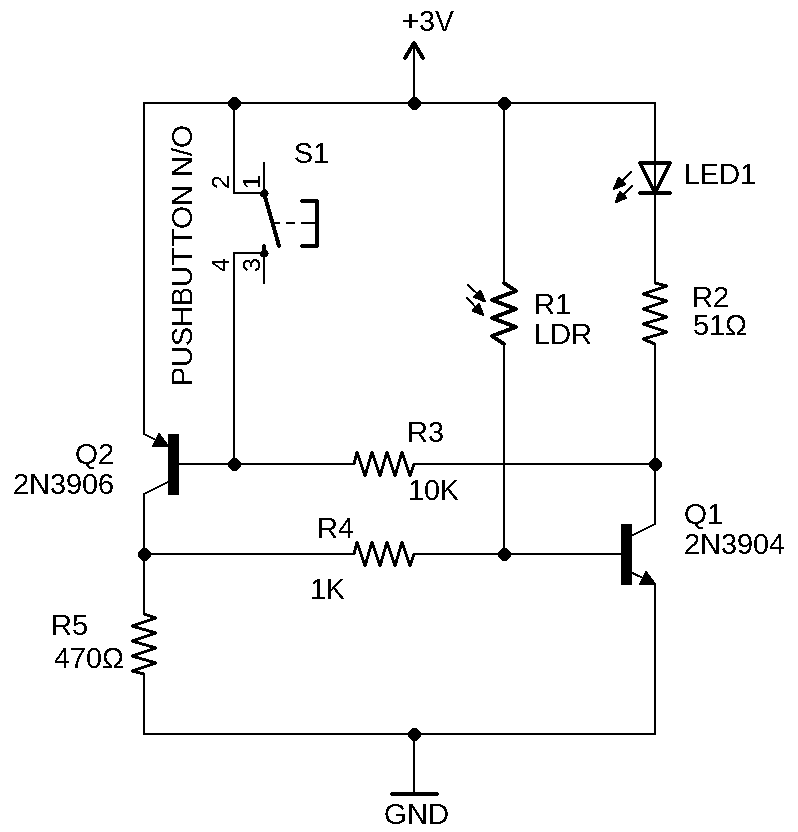
Flashlight Laser Tag Schematic:
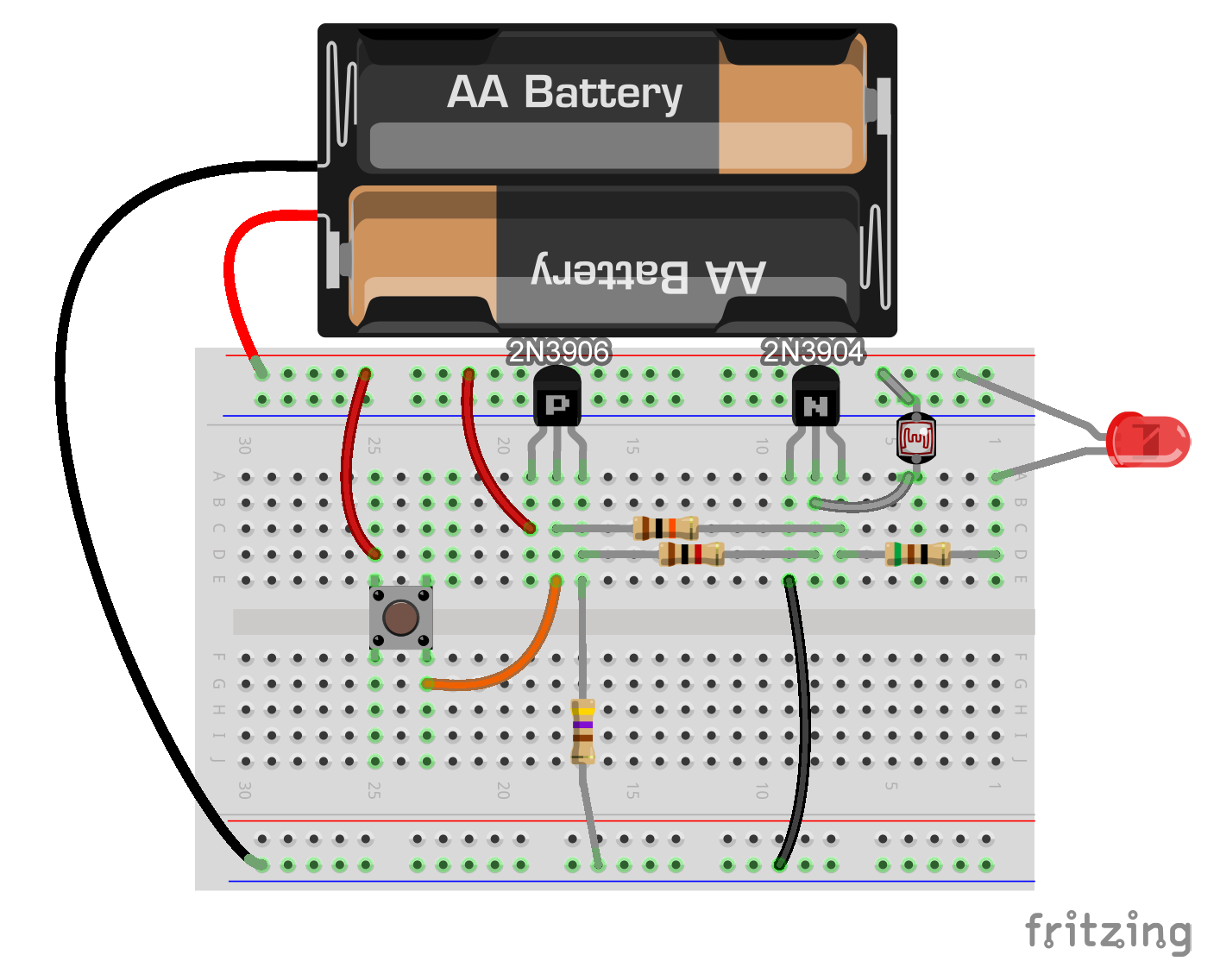
Flashlight laser tag breadboard diagram:
Introduction to the Circuit
The next two videos below show you how to build the circuit, first on a breadboard, and then how to solder the circuit together, so you can opt to watch either one. If you have someone who's handy with tools and soldering irons, invite them to build this with you.
Building the Circuit on a Breadboard
Soldering the Circuit Together
You'll need one of these circuits for every player, although you can get by with one kid having a flashlight (this is the "it" person) and the other running around wearing the circuit trying not to get "tagged". You can mount these circuits inside a soapbox or cardboard box with the sensor and light peeking out. Add a belt or wrist strap and you're ready for action!
[/am4show]
It may just be too bright in the room where you’re using the circuit. Or, you may have a bad connection. First, make sure all of your connections are good, then try out your circuit in a fairly dark room. If the LED still continues to glow no matter what, go back to a bright room and take a couple well lit pictures of your entire circuit and email them to aurora@superchargedscience.com. Be sure to mention the problem in your email.
When I hold the momentary switch down, even though there may not be light shining on it, the LED lights! I have tried covering the CdS cell completely, but the LED still lights! It was working before. What did I do?????
Sure, you can either replace LED1 and R2 with a buzzer, or put a buzzer in parallel with LED1 and R2.
Can you use a buzzer instead of the LED so that the person who is not it can keep his/her eyes on the path ahead instead of constantly glancing at the circuit?
If you have Brian’s “Electronics Essentials” kit, then yes you have everything needed for this activity. However, I recommend that you only build the breadboard version of the circuit. If you solder the parts, they won’t be available for Brian’s classes.
I have Brian’s electronics kit. Does that have most of the materials needed????
Yes, it’s included in the Diamond Science Mastery program in the Electronics I package (in the box labelled “D2”). Use the included breadboard to make the circuit. You’ll find the laser in the Electronics 2 package. Watch the first and second videos and you should have everything you need. Happy building!
Are the materials needed for this project included in any of the kits that come with the Diamond package?
No – it just helps you reset it do you can play again, since it’s a latching circuit. You can also just take out the batteries and stick them back in again.
Does it make a difference if you have a switch or not?
Two ideas… your wiring might not be correct (double check this by watching the video and going through your circuit again to check it over), or your resistor value might not be matched with the CdS cell you have. What happens if you change the resistor to a different value? Do you have one you can try from another experiment?
We’ve been able to build the circuit on a breadboard but when we put in batteries, the LED lights up without a light shining on it and we didn’t put a switch on it. Do you have any idea why?
Hey there! That’s a great idea… and yes we do exactly that! In Unit 14: Electronics, especially in Lessons 3 and 4. 🙂 Let me know if you need further help finding them.
Hi Aurora,
I was wondering if maybe in the future you could provide schematics for your electronics project? If after completing you classes the kids might want to do more, they would need to know how to read schematics. Additionally It would be helpful to those who can read, especially it there breadboard is not identical in its layout as yours. Thanks for all your amazing work! (and updating videos to work on iPad)
– One happy kid
It’s a resistor network that you are describing, but it may not be 4.7k. It’s best to get one from radio shack, or I am happy to send you one in exchange for a testimonial about our program. Contact me.
i have a 4.7 kilaohm resistor that is brown and is long and has 5 teeth sticking out will that still work?
Yes, you can always wire up a separate circuit using the same battery source for anything additional you want to run, like extra LEDs.
Actually my question is can you have 2 LEDs one that stays on all the time and on that lights up when light hits the DSC cell
Yes, when you wire up the circuit, the LED lights up until you reset it to start again. It lights up when you smack it with a beam of light – watch the end of the video to see how it works.
can you make an LED light up automaticly? for seperate teams and make the hit LED light up to?
Wow – what a cool project! We’re going to the store right now to get the parts. I can’t wait to make my whole family a set of these!!
Sure – you can do that. You can connect all the leads of one side of the cells to the battery and all the leads of the other side of the cell to the LED which then goes to the battery – that would be in parallel. Just scrunch the leads together and grab them with an alligator clip lead. Or can you hook them up one by one using a separate wire to go from one CdS cell to another and make a big loop with your circuit. Or use a large CdS cell instead of a bunch of little ones. What happens if you try a solar cell instead?
Hi,
I was just wondering if I could hook up multiple CdS to one curciuit. If I do, do i have to increase the voltage and change around the resistors, etc? This does sound overly complicated, so coud you pleasssssssseeeee make a video of this as an “alternative method” ?
Regrads,
Aashman (age 11)
Wow – I was surprised when this really worked. Thanks Aurora!
Did you make this circuit up yourself?
Yes, I sure did! So glad you like it! 🙂
This project is AWESOME!!! I’ve already built two and we’re making more tonight when Dad gets home. Your right – it’s way harder to tag someone out with the laser but I know we’ll get better at this. Thanks Aurora for such a cool project! ~Seth, age 11
From Mom: I’ve never seen such a simple circuit for this kind of project. I never graduated with an electronics degree or anything like this, but your instructions were easy to understand (I did have to watch it three times) and we were successful after a couple of tries. The best part is watching my son swell with pride when it worked for the very first time – I can’t tell you how amazing that was to see. I wish more learning was like this. Thank you for helping us all be better teachers to our kids. The sense of ownership and accomplishment he had with this project brought tears to my eyes. You’re right – you don’t get that from opening up a box. Thank you again!