 Once you’ve made the Pressure Sensor burglar alarm, you might be wondering how to make the alarm stay on after it has been triggered, the way the Trip Wire Sensor does.
The reason this isn’t as simple as it seems is that the trip wire is a normally closed (NC) switch while the pressure sensor is a normally open (NO) switch. This means that the trip wire is designed to allow current to flow through the tacks when there’s no paper insulating them, while the pressure sensor stops current flowing in it’s un-squished state. It’s just the nature of the two different types of switches.
However, we can build a circuit using a relay which will ‘latch on’ when activated and remain on until you reset the system (by cutting off the power). This super-cool latching circuit video will show you everything you need to know.
[am4show have=’p8;p9;p11;p38;p92;p20;p47;p107;p108;p76;’ guest_error=’Guest error message’ user_error=’User error message’ ]
Materials:
- relay (from Unit 11)
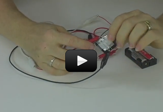
- your completed Pressure Sensor circuit
- SPST switch (optional)
Download Student Worksheet & Exercises

Use 9V for your batteries, the first switch is SPST, the second is the pressure sensor, the B stands for ‘buzzer’. The spring-looking thing is the relay coil, and the contacts are the three lines above the circuit hooked on either side of the second switch. Watch the video for real-time step-by-step instructions on how to build this!
Exercises
- What is a relay?
- What does the relay do in this circuit?
- Draw out a picture that shows how everything is connected in your circuit:
[/am4show]
Lol! The relay looks like a mini sewing machine