This lesson is for advanced students, and advanced 5-8th graders as well. For this lesson, you’ll need the Electronic Learning Lab by Radio Shack (or other similar electronics learning lab boards - there are lots of them available out there.) They come with tons of experiments that cover both basic and digital electronics projects! It includes everything you need for all the projects in these two lessons.

Since the mid 1980′s, digital electronics have slowly become an ever increasing part of our lives. And now, you’d be hard pressed to find any device that doesn’t use digital electronics. Digital electronics are in the TV you watch, your computer, your phone, your car, the appliances in your kitchen, and so much more. So, to help understand how digital works, we’ll be exploring digital electronics in this series of videos.

We are going to cover a lot of ground in workbook 2 beginning with learning about the basics of digital electronics. This will include learning what a bit is, what a high and a low are, basic digital gates, among other topics.

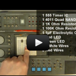
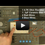
Next, we’ll move on to building digital electronic circuits using both digital ICs, and a few analog ICs along the way, to learn about adding in binary, making cool sounds, digital memory, bargraphs, among other things. We’ll also be learning about 7 segment displays, how they work, and how to use them. There are so many neat and cool experiments, I know you are going to have a lot fun. There’s a lot of ground to cover and I know you are just as anxious to get started as I am, so I’ll see you over at the electronics learning lab!

If you find your students are thirsty for more reading content that is provided in the project kit, then these are my three favorites. There are THREE books recommended (not required) for this unit at the 9-12 grade level. When your kids hound you for more projects, pick up these texts for further projects. Here they are:


Select a Lesson

Getting Started With Digital Logic 1
Digital electronics can be a lot of fun and there are some really cool components in the market. So to get us going, in this video we’ll take a look at what digital is and start looking at how it works.
Getting Started With Digital Logic: Logic Gates
Expanding on the first video for workbook 2, in this video we’ll take a look at logic gates, what they are, and how they work. This includes the AND gate, NAND gate, OR gate, and NOR gate.
Build a Simple Logic Probe
Time to start building some circuits, in this experiment we’ll use a 4049 hex inverter IC to build a simple logic probe. Logic probes are used to assist in debugging digital electronics.
Understanding Truth Tables
In this video we’ll take a look at truth tables, what they are, and why we need them. We’ll also build a simple circuit and construct a truth table from that circuit.
4001 Quad NOR Gate: Build a Simple LED Flasher
Okay, time to have some more fun with LEDs. In this experiment we’ll build a simple LED flasher and see how we can use two NOR gates to create an oscillator.
4001 Quad NOR Gate: Build a Fancy LED Flasher
In this experiment we’ll modify the LED flasher to use two LEDs and have an adjustable flash rate using a potentiometer.
4001 Quad NOR Gate: Build a Set-Reset Latch
Want to know how computers remember things? Well, in this experiment we will use two NOR gates to build a Set-Reset latch, which is a simple digital memory storage circuit.
4001 Quad NOR Gate: Build a Control Gate
Okay, let’s get a little deeper into electronics and build a control gate. We’ll see how we can use a logic gate to control when a circuit is active and when it’s not.
4001 Quad NOR Gate: Build a Latched Relay
In this experiment we are going to combine a SR latch with an power FET and build a latched relay. And, we’ll see how we can use low power components to control high power circuits.
4049 Hex Inverter
Now, let’s have some more LED fun. In this experiment we’ll see how to use three inverters to build a dual LED flasher.
4070 Quad Exclusive OR Gate: Build a Binary Half Adder
Want to see how computers add? Well, in this experiment we are going to use a exclusive OR gate to build a binary half adder to get an idea of how computers add numbers. This is a critical lesson in understanding binary and how binary numbers are added together, we’ll also expand on this experiment …
4011 Quad NAND Gate: How the NAND Gate Works
Let’s take a closer look at the NAND gate and how it works, so in this experiment we’ll build a circuit to test the NAND gate and also create a truth table to prove the NAND gate is working correctly.
4011 Quad NAND Gate: Make a Red-Green
More LED fun! In this experiment we’ll see who we can combine a 555 timer, a single NAND gate, and make an alternating LED flasher. This circuit will alternate (turn on and off) a green LED and a red LED.
4011 Quad NAND Gate:How to Make an OR Gate
There are a lot of different types of logic gates and in this experiment we’ll see how we can use three NAND gates to make an OR gate. And then we’ll test the gate and create a truth table to prove that the OR gate is working correctly.
4011 NAND Gate:Build a Simple Tone Generator
Let’s make some noise! In this experiment we’ll use two NAND gates to create a simple oscillator and tie that into the speaker and we’ll see how easy it is to make a tone generator using just a few parts.
4011 NAND Gate:Build a Better Tone Generator
The tone generator is nice, but we can make it better. So, in this experiment we’ll modify the tone generator from page 46 of workbook 2 to have an adjustable frequency and volume.
4011 NAND Gate:Build a Pulsating Tone Generator
Let’s take the tone generator a step further and add in a second frequency generator and pulse the tone out to the speaker. In this experiment we’ll see how to do just that.
4070 Quad Exclusive: Build a Binary Full Adder
A half-adder is nice, but it’s not providing all the information we need to fully see what’s going on. So, in this experiment we’ll build upon the half-adder from experiment 53 in workbook 2, and turn the half-adder into a full-adder.
4070 Quad Exclusive OR Gate
Digital locks are pretty neat and in this experiment we are going to build one. We’ll use a lot of different logic ICs to build a digital comparator, which can be used as a combination lock to protect valuables.
4066 Quad Switch: Getting to Know the 4066
Your Electronics Learning Lab includes a 4066 switch IC and in this video we’ll take a look at how this IC works by building a simple LED indicator circuit.
4013 Dual Flip-Flop: Build and Understand a Data Flip-Flop
Okay, let’s dive a little deeper into digital memory by taking a look at a data type flip-flop. We’ll see how this logic IC works by building a simple LED display interface and control the flip-flop using switches.
4013 Dual Flip-Flop: Build a Divide-By-Two Circuit
Would you like to see a digital circuit do a little division? Well, in this experiment we’ll build on our knowledge and build a divide-by-two circuit using an inverter IC the 4013 D-type flip-flop. This circuit is also the basis for the LED chaser circuit we’ll build later in the series.
4013 Dual Flip-Flop: Build a Binary 2-Bit Counter
Let’s take a look at binary addition and build a 2-bit counter. In this experiment we’ll modify the divide-by-two circuit we built in the last video to a 2-bit binary counter.
4013 Dual Flip-Flop: Build a 1-of-4 Sequencer
Time for some light chasing fun. In this experiment we’ll modify the divide-by-two circuit form the last video to an LED chaser circuit. This one is really neat and I’m personally excited to see this one in action!
4017 Decade Counter – Make a Switch Bounce Analyzer
Did you know switches are noise? And no, I don’t mean the noise they make when you turn one on or off, I mean they are electrically noisy. What this means is that when a switch changes state is creates a little wave of electrical spike that can cause digital electronics to misread the signal. …
4017 Decade Counter – Make a Totalizer
Now that you’ve seen switch noise, it’s time to look at a method to correct the problem. So in this experiment we are going to build a totalizer and add a capacitor to the switch to remove switch noise.
4017 Decade Counter – Build a Count-to-N And Halt Counter
In this experiment we’ll modify the totalizer we built in the last experiment to a count-to-n and halt circuit. This is a great demonstration of using electronics to operate a circuit until a specific number of events has occurred.
4017 Decade Counter – Build a Bargraph Readout
Let’s build a bargraph readout! In this experiment we’ll use two oscillator circuits to modify the switch bounce analyzer circuit to a bargraph readout.
4017 Decade Counter
The bargraph readout from the previous experiment is nice, but let’s make it better. In this experiment we’ll use three oscillator circuits to control the bargraph’s settings and also add in a tone generator.
4511 Seven-Segment Decoder-Driver
It’s been sitting there, and we’ve hardly touched the seven segment display. Well, in this video we are going to use the 4511 seven segment decoder to drive the seven segment display and a keypad to display different numbers. This one is going to be a lot of fun!
4029 Up-Down Counter
Let’s build a digital alarm! In this experiment we’ll modify the circuit from experiment 90, workbook 2, to be a digital alarm. The circuit will countdown and when it reaches zero, the alarm will sound. We’ll also add in a switch so that the alarm part of the circuit can be disabled.