Although you can’t see electricity, you can certainly detect its effects – a buzzer sounding, a light flashing, a motor turning… all of these happen because of electricity. Which is why electricity experiments are among the most frustrating. You can’t always tell where the problem is in a circuit that refuses to work right.


We’re going to outline the different electronic components (resistors, capacitors, diodes, transistors, etc) so you get a better feel for how to use them in a circuit. While we’re not going to spend time on why each of these parts work (which is a topic best reserved for college courses), we are going to tackle how to use them to get your circuit to do what you want. The steps to building several different electronics projects are outlined very carefully so you can really understand this incredible micro-world.


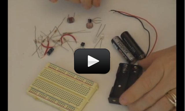
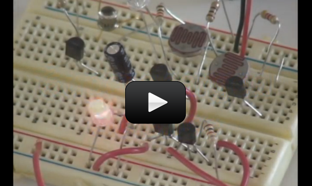
In this video, you’ll learn how to identify each electronic component.  You’ll also learn how to use a breadboard to quickly build circuits that can be easily changed.  Plus, you’ll learn how to make sure you don’t damage your components.


Before you use a breadboard, you need to know how the “holes” in it connect to each other.  Once you get this, they’re easy to use, but until you understand their secret, they can be totally confusing.  Be sure to pay attention to this part, and it will make things a lot easier.  Once you have this down, you’ll wire up a few simple circuits on the breadboard just to try out your new knowledge.


Which part is which? Click here to access a reference sheet so you can tell which resistor is which.


Please login or register to read the rest of this content.


In this circuit, we’re going to use a special kind of resistor, called a CdS photocell to detect light and dark.  When light is shined on the photocell, the LED will light up.  When it is dark, the LED goes out.  And with just a little light, the LED is dim.  Remember the explanation of how a transistor works?  We talked about having a small voltage (or current) control a larger one, kind of like turning the knob on a light switch dimmer in your house?  That’s what this circuit is doing.


The photocell is a kind of resistor that changes it’s resistance depending on how light or dark it is.  In this circuit, when it is light, the photocell delivers more current to the base lead of the transistor.   When this happens, the transistor allows more voltage to flow from the emitter lead to the collector lead, which in turn lights up the LED.  One resistor are simply used to reduce the amount of current that goes into the transistor (so it doesn’t get too much current)  if the photocell has a really low resistance because of how much light is on it.  The other one is called a pull-down resistor.  Think of it like a door closer spring for electricity.  A door closer closes the door when you let go of it (instead of leaving the door to sway in the wind).  A pull-down resistor makes sure that when the transistor is “off”, it will “spring” toward a connection to the negative side of the battery (a pull-up makes it spring toward the positive).


If this is all confusing, don’t worry.  It will make more sense as you build more circuits and look at more schematic diagrams.


Click here for Unit 14 (Lesson 1) schematics.


This light-actuated relay circuit will remain actuated for a brief time after you remove the light.  You can substitute a 1.5-3V buzzer for the LED if you’d rather have a loud circuit.


Materials:


  • breadboard
  • AA battery case
  • 2 AA batteries
  • LED
  • CdS photocell
  • transistor (2N2222A)
  • 4.7k resistor
  • 1k resistor
  • jump wires
  • wire strippers

Here’s what you do:


Please login or register to read the rest of this content.


Make sure you’ve already made the Light Actuated Circuit before starting this project!


Photoresistors (also called CdS photocells) are made of a material that reacts with light, very similar to solar cells.  When light hits the material, it knocks a few electrons loose. When you hook up the cell to a circuit, the electrons now have a place to go, and electricity flows through your wires. You’ll notice your CdS cell works when you shine a light on it from either the front side or the back side. If you want to use a phototransistor, make a note as to the frequency of light it’s been tuned to – some will only work with IR light (like your remote control or sunlight).


In this circuit, the LED is actuated only when the photoresistor is dark. If you want a faster response to your light, you can substitute a phototransistor for the photoresistor (CdS cell) and adjust the value of the 1-kOhm resistor (change it lower or higher, or use a potentiometer) to control the sensitivity.


This is basically the same as the light-actuated circuit.  The difference is that the transistor is connected to control power to the LED in the opposite way as the light-actuated circuit.  So, as there is more light on the photocell (and the base lead gets more current), the voltage to the transistor is reduced.


Click here for Unit 14 (Lesson 1) schematics.


Notice what is the same in the circuit, and what is different.


Materials:


  • breadboard
  • AA battery case
  • 2 AA batteries
  • LED
  • CdS photocell
  • transistor (2N2222A)
  • 4.7k resistor
  • 1k resistor
  • jump wires
  • wire strippers


Please login or register to read the rest of this content.


Do you remember the first time you tried to read a map? There were all those weird symbols and curving lines that you had to figure out before you could get anywhere. Electric circuits are kind of the same way… people use schematic diagrams to write down how their circuit is wired so others can build it, too.


Now that you’ve built a couple of the breadboard circuits, it’s time to figure out how to read the symbols and build a circuit from a diagram. At first, it may seem a bit overwhelming with all the strange symbols and lines drawn all over the page, but don’t worry – after a couple of circuits, you’ll be cruising through these like a pro.


The first thing you need to do is download the schematics (if you haven’t already) and then watch this video:


Please login or register to read the rest of this content.


This Flashing Circuit used to be a real ‘wowser!’ with students before LEDs become commonplace (around 1995). You’re going to build a circuit that has a control knob that will allow you to set the flash speed of the LED. You can try different LEDs or mini-lamps to see what kind of an effect you get. Are you ready?


NPN and PNP transistors are similar in that when current is applied to the base, electricity flows through them.  But, they way they are used is different.  NPN transistors are often used to control whether a circuit is completed by connecting it to ground or not, where PNP control the positive current going into a device (or portion of a circuit).  NPN transistors are often used where larger currents need to be controlled, because it’s easier for a transistor to control the ground side of a circuit than the plus power side of it.


So, why does the LED flash?  Remember, a capacitor is like a storage tank for electricity.  You fill it up, then empty it out.  But, it takes time to fill up and empty.  This circuit uses the time it takes to fill and empty as a delay for turning the LED on and off.  How fast it fills up depends on the value of the resistor that is connected to it.  We’re using a variable resistor, so we can adjust how fast it fills up, and thus adjust the flash rate.


Click here for Unit 14 (Lesson 1) schematics.


Materials:


  • breadboard
  • AA battery case
  • 2 AA batteries
  • LED
  • potentiometer
  • transistor (2N2222A and 2N4403)
  • 5.6k resistor
  • 1k resistor
  • 10k resistor
  • jump wires
  • wire strippers


Please login or register to read the rest of this content.


Resistors look like candy-striped hot dogs. Their job is to limit current to keep sensitive electronics from being overloaded. If you break open a resistor, you’ll find a pile of graphite. If you have a digital multimeter, draw a line on a sheet of paper with a graphite pencil, and place one probe near the end of the line. You can measure the change in resistance along the line with your other multimeter probe!


Make sure you’ve made the Light Flasher before starting this circuit. This circuit, the Audible Light Probe, is actually a very sensitive circuit that will emit all sorts of sounds reminiscent of junior high school boys locker rooms. The frequency from the speaker will change as the light intensity changes. One of the neat features about this circuit is that it will allow you to test different transistors (both PNP and NPN) to see (hear) the changes. You can also play with the capacitor and resistor values to change the range.


Click here for Unit 14 (Lesson 1) schematics.


TIP: If your tones won’t stop, or are too high to hear, try operating your circuit in a very dark room before adding the light. Can you get your speaker to *click*?


Materials:


  • breadboard
  • AA battery case
  • 2 AA batteries
  • LED
  • CdS photocell
  • transistor (2N2222A and 2N4403)
  • 1k resistor
  • 0.47μf electrolytic capacitor
  • 8-ohm speaker
  • jump wires
  • wire strippers


Please login or register to read the rest of this content.


Lie Detectors are electronic circuits that are able to measure your skin’s resistance. When you sweat (or if your skin is wet), the resistance is different than if it’s dry.


However since most people don’t sweat when they lie, this type of detector isn’t the most reliable type of detector around, but it’s one of the simplest to create. We’re going to build one from simple electronic components like resistors, capacitors, and transistors.


Our lie detector uses a speaker that changes pitch depending on the resistance of your skin – it’s much more entertaining than blinking an LED on or off. You can think of this circuit as more of a skin humidity indicator. Are you ready?


Please login or register to read the rest of this content.


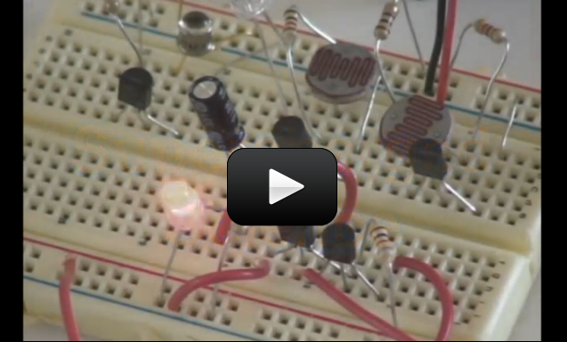
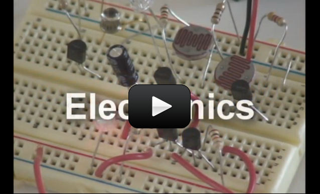
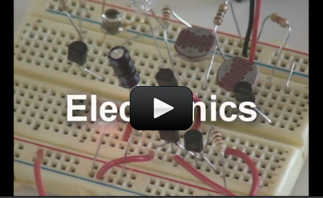
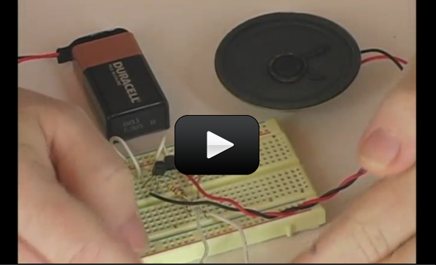
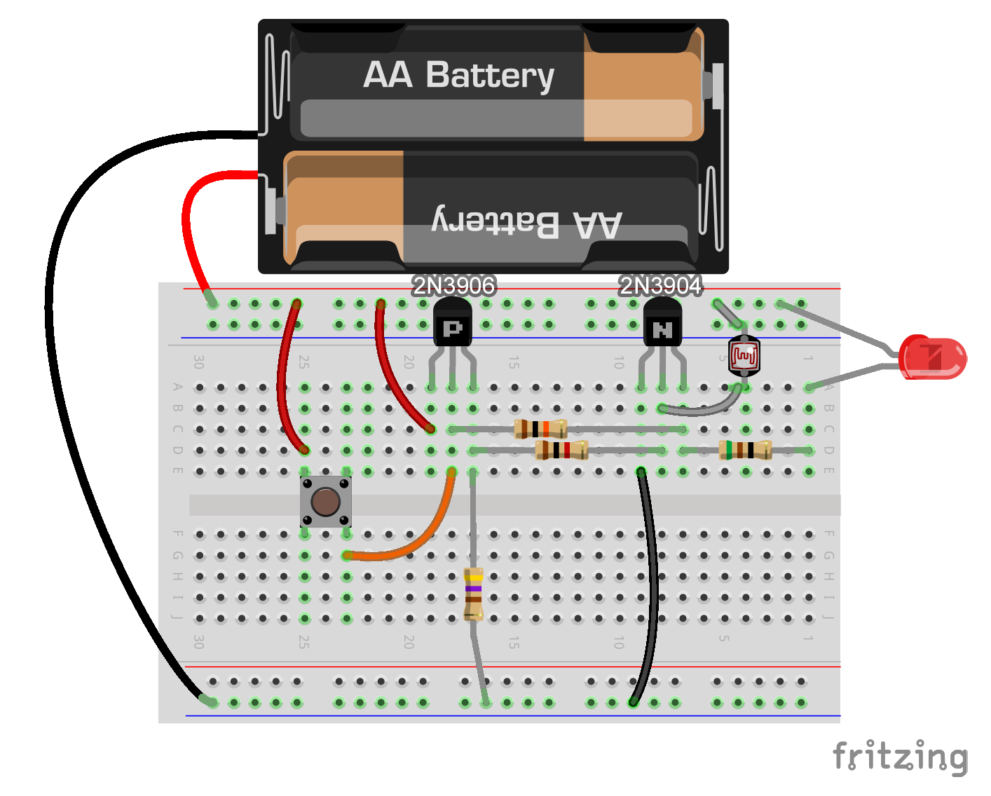
This super-cool project lets kids have the fun of playing tag in the dark on a warm summer evening, without the "gun" aspect traditionally found in laser tag. Kids not only get to enjoy the sport, but also have the pride that they build the tag system themselves - something you simply can't get from opening up a laser tag game box.
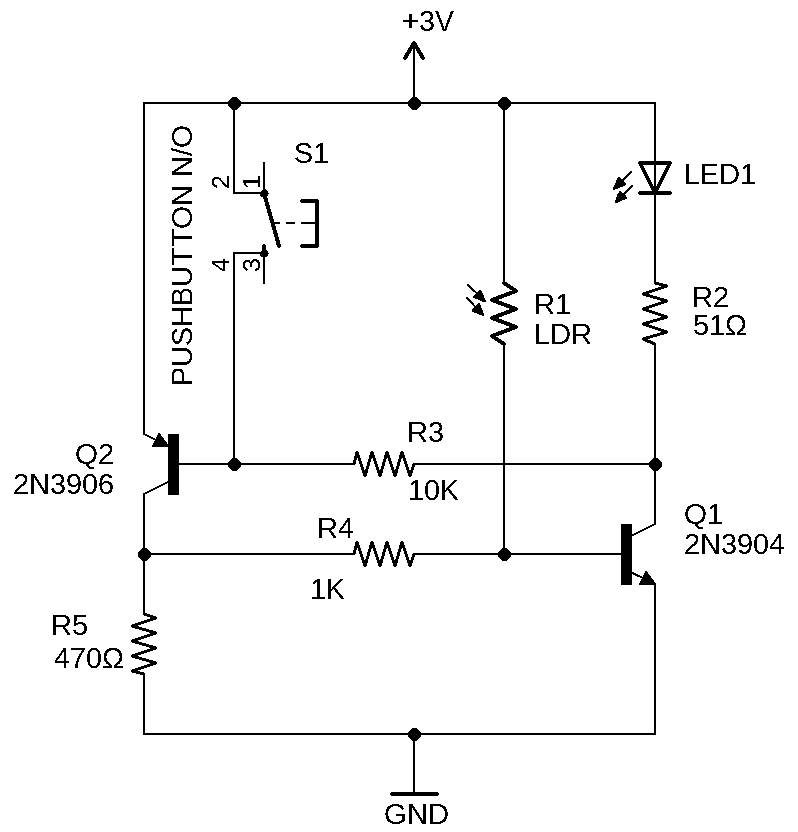
While real laser tag games actually never use lasers, but rather infrared beams, this laser tag uses real lasers, so you'll want to arm the kids with the "no-lasers-on-the-face" with a 10-minute time-out penalty to ensure everyone has a good time. You can alternatively use flashlights instead of lasers, which makes the game a lot easier to tag someone out.

This game uses a simple two-transistor latching circuit design, so there's no programming or overly-complicated circuitry to worry about. If you've never built this kind of circuit before, it's a perfect first-step into the world of electronics.

I've provided you with three videos below. This first video is an introduction to what we are going to make and how it works. Here's what you need:

NOTE: We updated this circuit in 2023 to reflect "best practices" when using transistors. 

Be sure to build this project as shown in the schematic and breadboard diagrams, and not as shown in the video.

The material list below is based on the new design as shown in the schematic and breadboard diagrams on this page.

The videos show how to build the old circuit, but are still very useful.

Materials (the list below builds one complete set per kid):

Flashlight Laser Tag Schematic:

Flashlight laser tag breadboard diagram:

Introduction to the Circuit


The next two videos below show you how to build the circuit, first on a breadboard, and then how to solder the circuit together, so you can opt to watch either one. If you have someone who's handy with tools and soldering irons, invite them to build this with you.

Building the Circuit on a Breadboard

Soldering the Circuit Together

You'll need one of these circuits for every player, although you can get by with one kid having a flashlight (this is the "it" person) and the other running around wearing the circuit trying not to get "tagged". You can mount these circuits inside a soap box or cardboard box with the sensor and light peeking out. Add a belt or wrist strap and you're ready for action!

Please login or register to read the rest of this content.