Back in the 1980s, MIT did some amazing work in the field of robots with legs. Here's a video compilation from the Discovery Channel and their own Leg Lab work:
To learn more, visit http://www.ai.mit.edu/projects/leglab/home.html
To learn more, visit http://www.ai.mit.edu/projects/leglab/home.html
I was digging through some old video files and found this hour-long video of a robot competition I attended, and thought you might be interested to see how much robots have changed (or not?) since then!
If you'll notice in the video below, there are no Arduinos, no VEX pieces... everything was handmade using basic electronics knowledge. In fact, the two robots that were communicating using laptops that were bolted right onto the robot was actually a really innovative idea!
This video was from an event about 20 years ago... was when I was still teaching engineering at the university, and just getting started teaching kids.
The hour-long version of the video was kind of long and tedious (it was just watching competition after competition), so I slimmed it down to just under two minutes so you could really get a taste for it. Hope you enjoy it!
Arduino Robotics
An “Arduino” is a micro-controller that really makes robotics a lot easier and fun to create. First designed in 2005 by an Italian company, these single boards were originally intended for students learning robotics.
The board consists of standardized connectors, which allow a whole host of interchangeable add-on modules (shields) to be used. It’s like the brains of a computer that you can add inputs (like sensors) and outputs connections (like motors) to.
Arduinos are not limited to student robotics. In fact, you’ll find them anywhere there’s automation, from telescope observatories to weather stations to smart home functions.
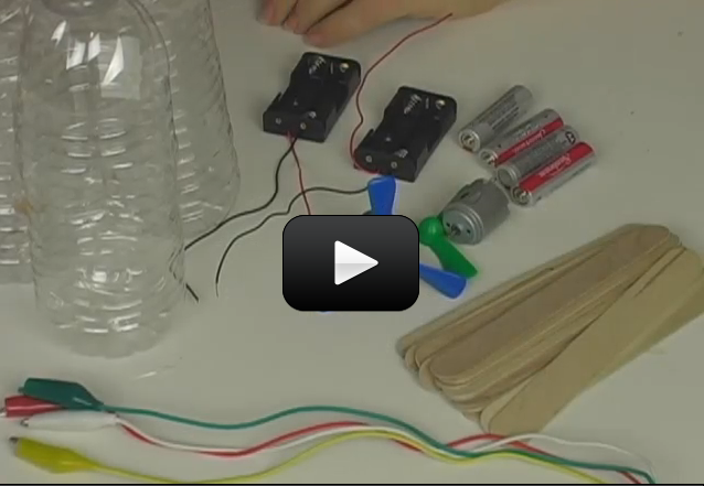
We’re going to learn how to transform an inexpensive Arduino board into a fully functioning autonomous robot with sensors, just like the one in the image above. This will take several steps, so watch the videos in order so you don’t miss a thing.

VEX IQ Robotics
The VEX IQ Robotics Competition for elementary and middle school students is open to teams of two or more kids who build a robot to compete in local competitions.
While it's really exciting and fun, it's easy to feel overwhelmed due to the open-endlessness, and that's what we're going to hep you with. Ready to get started?

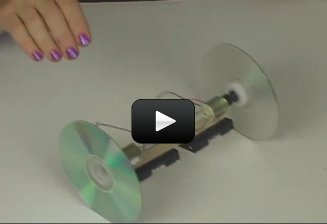
If you’ve ever ridden a two-wheel bicycle, you know that you have to not only pedal to move forward, but also balance in order to stay upright while you move.
Two wheeler robots are difficult to make because they need to balance in addition to carry out commands. The balance is done autonomously, meaning that the robot must be programmed to figure out how to balance itself.
We’re going to skip this complicated step and instead use gravity to balance for us. While this makes the robot a lot smaller, it’s also a lot quicker and easier to build than the model in this image. Are you ready?
Please login or register to read the rest of this content.
A cable car transports people or things in a vehicle that uses a strong cable to pull at a steady speed. Also called aerial lift, aerial tramway, or gondola, these are different from the cable cars associated with San Francisco, which use buried cables to move the car up steep streets.
The world’s longest working cable car is in Sweden and covers 26 miles. Sweden used to operate a 60-mile cable car, but only a 8.2 miles (13.2 km) of it still works today, however this section is the longest passenger cable car in operation currently.
We’re going to make a durable cable car that can travel as long as you have string for it to move along! It’s really a cool and simple project, and you can add cups or berry baskets below to transport cargo. Here’s what you need to do:
Please login or register to read the rest of this content.
The ferryboat was one of the ways folks got from island to island. Usually ferries make quick, short trips from one spot to another, picking up cars, people, or packages and transporting them across the water. In Venice, you’ll hear the ferry also referred to as the “water bus” or “water taxi”. Ferries that travel longer distances usually transport cars and trucks.
If you live in a waterside city or group of small islands, then the ferry is probably in your daily routine, because they are much cheaper than building complicated bridges or underwater tunnels.
Some ferries don’t have a “front” and “back”, but are double-ended and completely reversible, which allows them to shuttle back and forth across short distances without turning around. You’ll find these ferries in Australia, British Colombia, and Washington state.
There are many different types of ferries, including hovercraft, hydrofoils, and catamaran. Hydrofoils (shown in the image above) have special “wings” attached to the bottom of the boat that actually lift the boat out of the water when the speed increases. The special wing is designed to work in water and generate enough lift to move the massive boat out of the water so only a small part of the wing remains in the water to minimize friction (drag) force on the boat. With less friction, the boat can go even faster!
We’re going to make a simple ferry that works in the pool or bathtub. Don’t forget to add a remote control with extra-long wires!
Please login or register to read the rest of this content.
Catamarans are boats with two or more hulls that are strapped together and move by either wind power (using sails) or engine power. They are one of the first boats humans ever floated in. Catamarans are used when speed and large payloads are needed: their interesting geometric design (their balance is based on geometry, not weight) allows them to glide through the water with lower friction and carry more than single-hulled boats.
We’re going to create two different versions of the catamaran, mainly depending on how many water bottles you have available. Put these in a swimming pool and watch them zoom!
Please login or register to read the rest of this content.
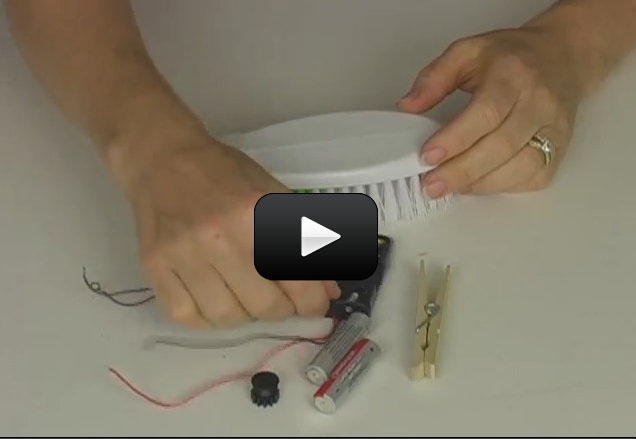
This robot as a BIG version of the tiny Bristlebot robot. Using an eccentric drive motor, this robot will show you how a cell phone vibrates by using an off-center weight being slung around by a motor. We built these types of robots in all sizes: from tiny toothbrush versions all the way to large commercial-sized sweeper brooms.
This project is just the right size to give you a fun robot that really works. It’s lightweight enough so you don’t have to use large, expensive motors or power supplies and worry about high voltage… so enjoy!
Please login or register to read the rest of this content.
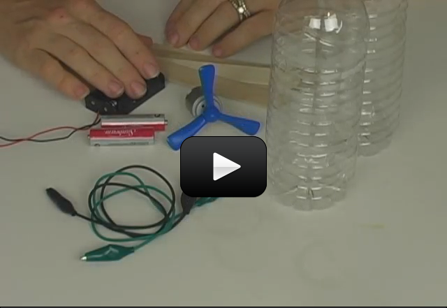
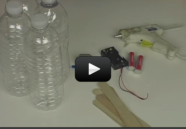
Amphibious vehicles is a craft which travels on both land and water. And it doesn't need to be limited to just cars. There are amphibious bicycles, buses, and RVs. Hovercraft are amphibious, too!
Amphibious crafts started back in the 1800s as steam-powered barges. In the 1950s, the German Schimmwagen was a small jeep that could travel in water as well as on land. The most popular amphibious vehicle on the market is the 1960 Amphibicar (photo shown left) and later the Gibbs Aquada.
The secret to making an amphibious vehicle is this: it must be designed so it floats in water (it must be watertight and buoyant) and robust enough to travel on land. Many amphibious creations either leaked, sank, or never made it off the drawing board. But that's what being a scientist is all about: coming up with an overall goal and figuring out a way to overcome the problems faced along the way.
We're going to build our own version using items like foam blocks and hobby motors. Are you ready?
Please login or register to read the rest of this content.
 The image here is the 2003 Gibbs Aqauda at full speed in deep water! It looks like it’s just skipping along the surface, doesn’t it?
The Gibbs company uses auto, marine, and propulsion technologies to build water-land vehicles used mostly by the military. But wouldn’t it save time to cut through the traffic on the bridge if you could skim through the water?
One of the main issues with amphibious vehicles is that they are painfully slow – both in the water and on land. (Although the 2003 Aquada gets up to 30 mph in water.)
The other issue is safety – the lift from the bow on a boat is needed to avoid plunging, but on a car you don’t want the front end to lift at high speeds. Also a boat distributes the load evenly across the hull while a car has concentrated loads where the suspension is attached to the frame.
 The Aquada car uses a 160 hp engine for land and a compact jet that produces 2,000 pounds of thrust. It broke the record for crossing the English Channel by four whole hours (third image below with the orange boat in the background).
And if the car goes fast enough, you can pull a waterskier.
The Gibbs company has also invented the Humdinga, which is for military use, as it has four-wheel drive at can cruise at 40 mph on water, as well as the Quadski, which travels at 50 mph on land or sea.
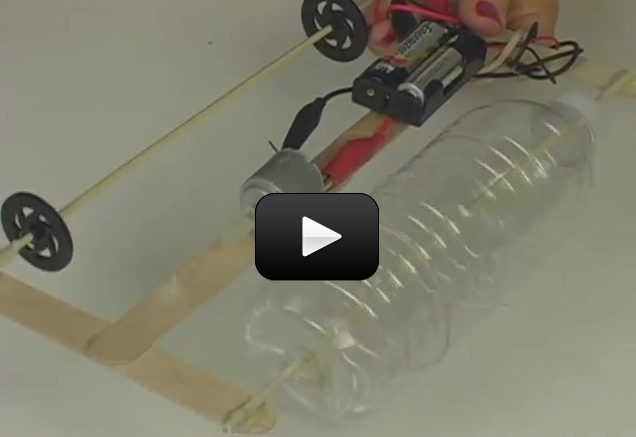
 We’re going to build our own model, though not with a jet engine. We’re going to use a motor, wheels, floats, and wires to build a real working model you can use in the tub tonight. Our model is also going to have a transmission that will enable you to get two different speeds using very simple materials. Are you ready? Here’s what you need to do:
Please login or register to read the rest of this content.
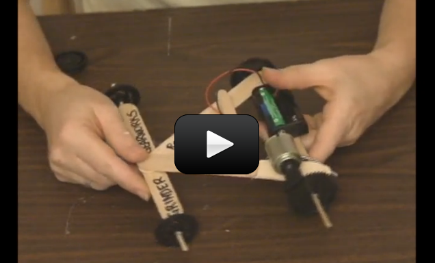
 Have you tried sticking a plastic wheel straight onto a motor shaft to create a race car? The first thing you’ll find is that the shaft is usually so slick that it doesn’t stay attached to the wheel without a ton of glue. And IF you’re able to attach the wheel to the motor firmly, it usually doesn’t have enough ‘oomph’ to turn the wheel without a push-start. The trouble is that you’ve got too much speed and not enough torque at the wheel.
The motor will generate the certain amount of power, but you can use that power in different ways. For example, a fan needs to be turning at high speed to be of any use, so it makes sense to simply strap a propeller onto the shaft and power up the motor. However, if you need a motor shaft to spin more slowly and with more ‘oomph’, then you need to add a couple of gears to help you do this.
When we build these race cars with college students, we made larger versions that could really transport them across the parking lot. Only instead of a tiny hobby motor turning the pinion (the gear attached to the motor shaft) as we’re going to do in our experiment here, the students powered their ride-on cars with a battery-powered drill they had to hold while riding it across the floor.
The biggest challenge students faced was selecting the gears. Depending on the student’s weight and rolling friction of the wheels, they would need to find the right gear combo for their car. The main thing to keep in mind is that you always trade speed for torque (twisting motion).
In the case with gears, the power is always the same (from the drill), but we slowed the rotation speed way down to increase the amount of torque (how much ‘oomph’ a wheel had to turn) in order to get it rolling. We’re going to experiment with this idea by creating our own geared race cars. Are you ready?
Need help finding gears?
Please login or register to read the rest of this content.
 Are cookies out of reach in your house? When I was a small kid, the top of the refrigerator seemed MILES away… until I built a robot arm out of toothbrushes, popsicle sticks, and cardboard to reach it for me!
I’ve upgraded my old idea to include a motorized linear actuator so you can see how real robot engineers create linear motion (back and forth along a straight line) from a spinning motor. The motor AND nut both need to pivot for the claw to work, so take special note as to how the linear actuator (the scissors-looking thing) is built.
Please login or register to read the rest of this content.
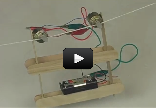
 Radio control (RC) is a 100 year-old technology. RC requires both a transmitter and a receiver. The control box sends commands to the robot the same way you change channels on the TV with the remote.
The difference between RC (radio control) and IR (infrared control) is in the frequency of the signals. With the radio controller, the light waves that carry the command information are lower energy, lower frequency signals. The TV remote uses higher energy, higher frequency infrared signals called CIR (consumer infrared).
Both RC and CIR require circuit design at a college graduate level. However, wired remote controls are well within the reach of any young budding scientist.
Please login or register to read the rest of this content.
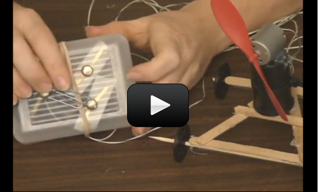
If you've made the waterbot, you can use this wired remove to make the motor turn both forward and reverse. All you need is an extra set of wires (telephone cable with two wires in it work great, or else twist two long wires together... they can be as long as you want.) Enclose the whole thing in a plastic box (I like to use tupperware or a soap box) and drill three holes in the top for the brass fasteners and one in the side for the wire and you're all set!
Materials:
Materials:
- your robot that you want to control (use any from this section)
- index card
- 3 brass fasteners
- 1 paper clip
- 4 additional alligator clip lead wires
- optional: plastic soap container
- optional: drill with drill bits
 Building the perfect robot for the right job.
If you’re new to robotics, LEGO makes it easy to build robots.
Even if you think you’ve outgrown LEGOs, take a second look at the inventions below that I’ve created. Many scientists and engineers got their start building with LEGOs! My kids and I share many LEGO sets together, and my absolute favorite is the 1999 Lego Mindstorms set.
We still use it to build and program robots today! But don’t feel limited to this set, as it’s hard to find nowadays. Use this page as a source of inspiration for your own inventions. Although these are images and not videos, do you think you can still figure out how they move?
 Tabletop Cleaner
A combination of the Ultimate Builder’s Set and my own creativeness and a differential light sensor (see below under “sensors”), this little guy can stay on a tabletop with right and left edge detectors, rear edge detector, and avoid obstacles with a left and right bump touch sensors, and can track a beam of light or find a light source using Michael Gasperi’s differential light detector. Using six sensors mulit-plexed into three available input ports on one RCX, a little creative programming, and three motors (one for the brushes, two for the drive) makes for a cool project!
 The Claw IV
One of the first things I’ve built from the Mindstorms box: I added pneumatics and a ball, and suddenly I have a 4-axis grabber arm with a pneumatic claw that picks up balls from one location and deposits them to the target every single time! I must add that if it were strictly open-loop program, it would miss after the second or third try, as it never quite comes back to the same spot. This MEGA CLAW uses four sensors, five motors (three for the three-axis movement, one to operate the pneumatics valve, one as a pump to keep the air tank stocked), one RCX, and one Scout (to handle the extra motor ports). Sensors detect the mechanical limits of the arm.
I initially wanted to make a 5 or 6-axis arm, but decided to wait until I understood how to get these pieces to fit together more efficiently.
 Max the Hexapod
I was so intrigued by the idea of a six-legged walker that I went right to the source – Flik by Nick Donaldson and Hexapod by JP Brown and made JP’s posted version of a single RCX Hexapod. It worked wonderfully! It took every last LEGO piece I owned to put Max together, as he’s a rather large robot – over 2 feet long, not including the whiskers.
 |
 |
| Aft Articulation Point | Forward Articulation Point |
Killough Platform

This is a Killough drive system from Macs Robotics Page. This platform can simultaneously rotate while driving forward. Think of how an office chair’s wheel base rotates around while you push the chair across the
room.

Same assembly three times make up the structure of this amazing robot platform.

Synchronous Drive Platform

This is a Synchro motor drive system also inspired by Building Robots with LEGO Mindstorms by Mario Ferrari et al. The coolness behind this system is the robots ability to turn its wheels in place without
turning the platform – hence this robot does not have a “front”, “rear”, “left”, or “right” – it goes in all directions!

Wheel assembly – each wheel is powered and can change orientation.

Top view – note that this robot was built upside-down!!

Tricycle Drive

Yet another Building Robots with LEGO Mindstorms inspired design. I did not have an RCX free when I built this, so I plugged it into the Scout and made both motors go forward. What was interesting about this was the vehicle initially went straight, then slowed and turned, then reversed direction in the turn, went backward, and began to turn again. One motor controls the drive, and the other controls the front wheel’s orientation. So when someone asks, “Can you build a car to go forward and reverse without reversing the motors?” you can say “Yes!”

Twelve-Legged Robot

This robot was inspired by Building Robots with LEGO Mindstorms by Mario Ferrari et al. The idea is to make a walker platform stable enough to turn tight corners while line-tracking. The only improvement I would do next time is to couple the motors (independent motors – one per side – in above photo) so it does not have a gradual turn while it walks!

MIBO

From Jin Sato’s book, The Master’s Technique, we created MIBO, a LEGO version of SONY’s AIBO – a robotic dog that can sit, shake (sort of), and shuffle along the floor. He barks (more like a beep, really), and is lots of fun!!! We’re adding non-LEGO parts, such as a wireless camera and sound sensor for further abilities for MIBO. (Chasing ball and following a whistle?) We’re really excited about MIBO and thank Jin Sato for all his hard work!
|


SHRIMP
 |
The SHRIMP is a high-mobility wheeled rover designed by the Autonomous Systems Lab in Lausanne, Switzerland. This innovative rover is capable of climbing over objects 2.5 times its wheel diameter!
 |
 |
 |
 |
 |
Whiz
Whiz is a “whiz with sensors!” robot geared for a complex game of RoboTag. This amazing robot is capable of exploring and reacting to its environment! Whiz is loaded with a differential light sensor to seek and find
light, a sound sensor to detect and react to sharp sounds, a line-detecting sensor mounted on the front for staying on a tabletop or within a black-outlined rink, and it can avoid obstacles by knowing which bumper – front or back – is triggered.
 |
Close-up views of the cool stuff:
 Differential Light Sensor |

Sound Sensor
Due to port limitations, I’ve plugged in a relay to switch between the sound and differential light sensor. The following ports are connected:
| Input 1 | Touch Sensors (both) |
| Input 2 | LEGO Light Sensor |
| Input 3 | Differential Light Sensor and Sound Sensor |
| Out A | Left Motor |
| Out B | Relay and LEGO Lamps (optional) |
| Out C | Right Motor |
 Front View(Two “eyeballs” are CdS light detectors in the differential light sensor) |
 Rear View (see the microphone?) |
 Top View (Blue box on left side is the relay) |
 Right Profile (Rear -> Front) |
 Left Profile (Front -> Rear) |
 |
|
Homebrew Sensors & Actuators
These sensors were adapted from Extreme Mindstorms: An Advanced Guide to Lego Mindstorms by Dave Baum, Michael Gasperi, Ralph Hempel and Luis Villa. Many thanks to all these wonderful inventors for their genius!
 |
This differential light sensor (as described in great detail in Michael Gasperi’s section of the book mentioned above) does a wonderful job of being a “smart sensor”. What would normally take 2 of your 3 sensor input ports to tell which way a light source is (to the left or right), this one tells you the difference and takes only 1 input port! You don’t need the full capacity of the LM324N – if you have a 358 handy, use it. The larger the CdS photocells, the better it reacts. This sensor is excellent for tracking a light source!! Currently used on Whiz. |
| A sound sensor initially seemed like a silly idea – especially when Michael Gasperi pointed out that it turned your expensive LEGO robot into a clapper. But then, during a game of RoboTag, we realized that it might not be such a bad idea. It would be handy to have one robot beep and the other listen and search for it. It worked pretty well for our application, and allowed us to use multiple robots to search for different characteristics (light, sound, touch, temperature…). Currently used on Whiz. |
 |
 |
I just had to know what was inside the expensive little light sensor that comes with the RIS. I was very excited when I found the schematic online and went to work right away. I am lucky enough to have a lot of parts on hand, and have noted some standard parts you can use if you don’t have the oddball ones mentioned in the schematic. Works great!! (Not currently used on Whiz) |
| I figured, if the sensor above can see light, why not add in IR capabilities and find out if it can see the difference between white and black? Take out the phototransistor (the transistor in the schematic without a base) and insert an IR detector. Add in the LED everyone’s always taking out – but be sure it’s an IR or visible red LED (red LEDs often also emit in the IR range, and you can see if they are on). If you wrap the detector in electrical tape to shield it from side-lighting from the LED, it works more accurately. It has a drop 15-20 (out of 100) between black and white, depending on your lighting conditions. Good enough for line-tracking! (Not currently used on Whiz) |
 |
 |
If you’re short on input ports, and you’ve got two touch sensors to wire to only one port, consider this: wouldn’t it be nice if the RCX read one value for one sensor, and a different value for the second sensor? To make one sensor read differently than another when both are plugged into the same input, you’ll need to make a special wire for the connection. Solder in a 22k resistor at the end of one of the wire leads just before it goes onto the electric plate, and your touch sensor will read about 50, whereas your straight connection (using the black wires that came with your RIS set for connecting sensors) will read 100. When you program, pretend it’s a light sensor reading two different values. Currently used on Whiz. |