

This Flashing Circuit used to be a real ‘wowser!’ with students before LEDs become commonplace (around 1995). You’re going to build a circuit that has a control knob that will allow you to set the flash speed of the LED. You can try different LEDs or mini-lamps to see what kind of an effect you get. Are you ready?
NPN and PNP transistors are similar in that when current is applied to the base, electricity flows through them. But, they way they are used is different. NPN transistors are often used to control whether a circuit is completed by connecting it to ground or not, where PNP control the positive current going into a device (or portion of a circuit). NPN transistors are often used where larger currents need to be controlled, because it’s easier for a transistor to control the ground side of a circuit than the plus power side of it.
So, why does the LED flash? Remember, a capacitor is like a storage tank for electricity. You fill it up, then empty it out. But, it takes time to fill up and empty. This circuit uses the time it takes to fill and empty as a delay for turning the LED on and off. How fast it fills up depends on the value of the resistor that is connected to it. We’re using a variable resistor, so we can adjust how fast it fills up, and thus adjust the flash rate.
Click here for Unit 14 (Lesson 1) schematics.
Materials:
- breadboard
- AA battery case
- 2 AA batteries
- LED
- potentiometer
- transistor (2N2222A and 2N4403)
- 5.6k resistor
- 1k resistor
- 10k resistor
- jump wires
- wire strippers
Please login or register to read the rest of this content.
The 10KΩ potentiometer and the 5.6KΩ resistor act as a voltage divider and control the charge rate of the 10µF electrolytic capacitor. Keep in mind that the 2N2222 is a NPN transistor, which responds to a positive voltage on the middle pin (the base). When the capacitor reaches .7 volts, it activates the 2N2222 transistor.
Up to this point, the 1KΩ resistor has been holding the base of the 2N4403 transistor high. The 2N4403 is a PNP transistor, which means that it activates when the base is dropped towards ground.
When the 2N2222 transistor activates, it begins to drain the capacitor and it grounds the base of the 2N4403 transistor, causing it to go active. When the 2N4403 transistor goes active, it provides a positive connection to the LED, causing it to glow.
The LED continues to glow until the capacitor drains and causes the 2N2222 transistor to deactivate.
For more details and lessons on transistors, please take a look at Unit 25.
Hi. Could you please explain how all the components work together in more detail? I would like to understand how they all work together in this circuit. THANK YOU!
Yes, but their potentiometer fits on to the breadboard so you don’t have to use alligator wires. It looks like this: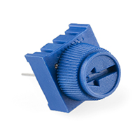
Does the future vision kit come with a potentiometer? We don’t see it.
Can you send me a short video and close-up images so I can help? It’s hard to help troubleshoot a circuit just over text! Send it to [email protected]
I tried all your suggestions and my LED still doesn’t flash- it just stays on. 🙁
Could the type of LED I’m using be the problem? (I’m using a recycled LED cut from a LED-bike-wheel-light.)
Here are some things to try:
1) Use a fresh pair of batteries
2) Ensure you are using the exact part numbers for the transistors and that you have the 2N222A and the 4403 in the proper locations (they aren’t interchangeable).
3) Ensure you have the capacitor plugged in the correct way.
4) Ensure you’re using the exact valued parts as shown on the schematic diagram.
5) Double check all your connections against the schematic diagram.
I have remade this entire circuit over again 5 or more times now, and my LED will not flash!!!
Can you please help me? The LED remains on, but there is no flashing. I switched out my 10k resistor for a 1k resistor to see if that would make a difference, but it didn’t.
Yes, it actually will change how your circuit works to swap out components! It’s actually kind of fun, and near the end of the videos in this section, I give suggestions for how to do it.
For your specific question, I am not sure about the “B” when you say “B1k” potentiometer. Did you get the kit from us for this experiment? (It’s in the Diamond Science Mastery program.) If so, then you’ve got the right one. If not, don’t worry – you can still get it to work just fine. a 1k potentiometer should work just fine, but I am wondering about your speaker. Is it 8-ohm? Can you send me a picture of your project so I can help more? It’s hard when it’s just written in text like this. Send me any details/photos/videos to [email protected]
We think we are using the wrong potentiometer, as with the one we are using the led just dims. We tried with a speaker as well, and the frequency of the sounds does change but not that much.
Ours say B1k is it supposed to be that one? does it matter?
The type of LED you have will have a different amount of resistance, and by moving where that resistance is in the circuit will have a different effect on ho wit works. Basically, all LEDs are not the same… so you have to be creative and flexible in your electronics design. Does that help?
at one point in the video`you said if the LED didnt light up, move the resistor to the positive side of the breadboard. I did, and it worked, but i dont understand why.
Did you get the resistors in the right spot? Also make sure that your transistor is in correctly (and didn’t get hot when you had your circuit on). Watch the video again and trace through your circuit step by step, and let me know if you still have trouble!
The only thing our potentiometer does is turn the light on, turning it doesn’t effect the light at all. I’ve added a few different resistors, but it either goes all on with one resistor, or all off with another one. Any suggestions?
No, not easily. A transistor is one of the basic electrical components that make up other components, like integrated circuits.
can you make a transistor?
Both schematics are in the same file. The light flasher is on page 3 and has two transistors and a potentiometer, while the light actuated needs to sense light so that’s where you’ll find the CdS cell. The name for each circuit is printed at the bottom of the page when you hold it right-side up. Does that help?
sorry for another question is the Schematics sopposed to have a cds cell in it I looked at both the light acuated circut and the flashing circut and it looks like there both the same.
Sure – how do you think you’d add them in?
Yes, and you’ll learn how to do that in the more advanced lessons in Unit 14. You will need a wall adapter that changes AC current to DC and steps it down to the voltage that you need for your circuit so it doesn’t fry your components.
is there a way to plug this into the wall
is there a way to make this project with more than one LED like christmas lights?
These transistors are so versatile, I am not surprised. Thanks for the share! I’ll ask my electronics techie and let you know what he says…
we found that our 4403 transistor worked the same both ways in the first bit of the experiment, unlike what you said. We were wondering if maybe it had something to do with the fact that we only had a 100-ohm resistor, not a 1-k-ohm, connected to the base. -Evan Larson