 This project is for advanced students. Make sure you’ve completed the Police Siren project first!
This is my favorite burglar alarm because it’s innocent-looking, hair-triggered, and completely obnoxious. Here’s what happens: after you build this circuit, you hang the wire loop around a metal doorknob, add the battery, and stand back. When an unsuspecting thief comes into your room, the alarm sounds as soon as they touch the other side of the door knob… and presto! You caught your burglar.
This circuit uses an IC (integrated circuit) called the LM324, which is a quad op-amp (operational amplifier), which produces a voltage that many times larger than the voltage difference between the inputs. Created in 1972, these low-power op-amps are actually four op-amps packaged into one. Although they are commonplace today in many electronic devices, they first started out in the 1940s as vacuum-tube devices at Bell Labs.
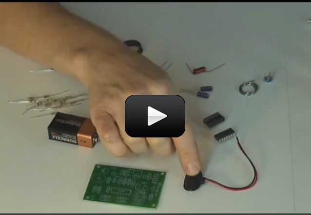
Are you ready to build a super-cool burglar alarm? To make this project, you’ll need to Door Knob Touch Alarm Kit, soldering equipment, and basic tools (scissors, hot glue gun, drill, wire strippers, pliers, screwdriver). (Don’t know how to solder yet? Click here for a lesson!)
Please login or register to read the rest of this content.
Solder is used to permanently hold parts onto the circuit board, while also providing the proper electrical connection. For a detailed explanation on soldering, please visit Unit 25 and watch Brian’s Soldering Basics Videos.
Why do we need to solder? [9 years old]
This it is in the shopping list for this unit, and it’s also included in the SMP Diamond program.
Where do I get the kit
The only # I can find is, C9018 , We need two, Is that enough info.?
Tell me specifically which transistors you are missing, and I’ll see if I can contact the company and get you replacements. I’ll need part numbers and identification numbers for the exact ones you want so they get it right the first time.
We need two more transistors,we have-C1815-but we need the rest, could you please send us a link to a website that we could buy them from? Thanks.
Look in the main shopping list for Unit 14 and you’ll find an online order link.
Hi Aurora,
I was wondering how to purchase the kit for the “Door Knob Touch Alarm.”
Thanks so much. (-:
Ooooops! Looks like a typo in the video, not with your kit! So sorry about that. The C1 capacitor should be 331 (not 330), which is 330 pF as shown in the video at 16:22. I totally apologize for the confusion. Here’s a capacitor chart so you have it for your reference.
The video says to use a ceramic capacitor 330 but we only have a 331, 332, and a 103 in the kit.
that is so cool!!!!!!
sebastian
Yes it’s in the Electronics 3 package. 🙂
Is this kit included in the diamond science mastery?
The e-Science online learning program has two different levels: K-8 and K-12. The higher level is appropriate for advanced 5-8th graders as well, as it includes textbook downloads and more involved projects than you’ll find in the K-8 section. Any projects/activities which involve flames, power tools, chemicals, soldering, or are just harder to do skill-wise are in this section (the underwater ROV robot, advanced robots, electronics, advanced chemistry experiments, etc.) all fall into this category. You can see the difference in the access levels when you find an experiment that says “This experiment is for grades 9-12.” as you won’t be able to access the content or watch the accompanying video with the K-8 access. You can always request an upgrade/downgrade at any time – just send us a request.
Do you have a video for this so it is easier to understand? By Skylar (6th grader)
Troubleshooting FAQ:
a. Try adjusting VR10K as described in the directions.
b. Make sure everything on the board is soldered well.
c. Double-Check the value of each part and make sure they are in the right spot. Verify that the two electrolytic capacitors are in the right way.
d. Check that transistors (9018’s and C458) are in the right way and leads are not touching each other.
e. Make sure the 4148 diodes are in the right way.
f. Make sure that the IC (LM324N) is plugged in the way the instructions describe, and that none of its leads are bent underneath it.
g. If none of these fix it, send us an email.