 This project is for advanced students. Make sure you’ve completed the Police Siren project first!
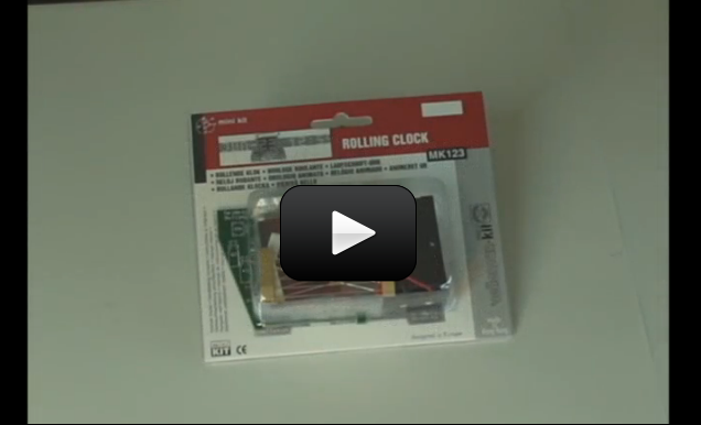
This is a really cool project, because it uses a microcontroller chip. This is a whole computer on a chip. The chip already has software loaded on it. It’s programmed to do just one thing: Keep time and make a clock go. A new component in this circuit is a crystal. This is the silver metal thing. It has a piece of quartz crystal in it. What’s cool about it is that if you apply voltage to it, it vibrates at a very precise frequency, which makes it ideal for keeping accurate time. These are used in virtually every electronic clock you can find (and anything else that requires precise timing).
While this IC chip is programmed to be a clock, the same chip could be re-programmed to scroll a text message across the display. If you really get into these types of circuits, you can learn to program microcontroller chips yourself from a regular computer (just like you do with a flash drive). So, remember, someone programmed this chip to be a clock, but all it really does is take inputs (electrical signals going in from things like the buttons and crystal), “process” them, and then create outputs (light up the LEDs in a certain pattern) based on its calculations.
To make this project, check the shopping list for Unit 14.
Please login or register to read the rest of this content.
You can probably still have it work just fine. Send me a picture (mailto: [email protected]) with a clear close-up of what’s going on and I’ll see what suggestions I can make.
We were soldering the lights on and one of the solder pads actually burnt, it turned black. We only held the soldering iron on for a max. of 2sec.. I did not want to solder all the rest of the lights on if it was not going to work, so will the project be ruined now?
The e-Science online learning program has two different levels: K-8 (this is the one you have) and K-12. The higher level is appropriate for advanced 5-8th graders as well, as it includes textbook downloads and more involved projects than you’ll find in the K-8 section. Any projects/activities which involve flames, power tools, chemicals, soldering, or are just harder to do skill-wise are in this section (the underwater ROV robot, advanced robots, electronics, advanced chemistry experiments, etc.) all fall into this category. You can see the difference in the access levels when you find an experiment that says “This experiment is for grades 9-12.” as you won’t be able to access the content or watch the accompanying video with the K-8 access. You can always request an upgrade/downgrade at any time – just send us a request.
Hi Aurora, I really want to do this experiment but I can watch the video or see the things needed. 🙁 Is there a link for this experiment?
Thanks Raena
Troubleshooting FAQ:
a. If the clock doesn’t do anything, try it with a battery as well as the AC adapter.
b. Make sure everything on the board is soldered well.
c. Double-Check the value of each part and make sure they are in the right spot. Verify that the two electrolytic capacitors (C4, C5) are in the right way.
d. Check that the voltage regulator (VR1) is in the right way and leads are not touching each other.
e. Make sure the diodes (D1, D2, D3, D4) are in the right way.
f. Make sure that the IC (PIC16C54) is plugged in the way the instructions describe, and that none of its leads are bent underneath it.
g. If just a few LED’s don’t light up, make sure they have been soldered in the correct direction. If they still don’t work, they probably got overheated during soldering and will need to be replaced.
h. The AC adapter connector is delicate – don’t push too hard to plug it into the clock. (Feel free to use some superglue to hold it down). If it comes off and you can’t just solder it back on because the solder “pad” came off with it, scrape some of the green solder-resist coating off the circuit trace it was soldered to. Then, either solder it back to that, or remove the connector completely, then connect short wires from where it was connected to the connector itself. This way, the connector will be at the end of the short wires, and not attached to the board anymore.